Laser radar system

Active Publication Date: 2015-01-08
ELECTRONICS & TELECOMM RES INST
View PDF9 Cites 68 Cited by
  • Summary
  • Abstract
  • Description
  • Claims
  • Application Information

AI Technical Summary

Benefits of technology

[0006]The present invention provides a laser radar system that may minimize an effort such as optical path alignment between a light transmitting path and a l

Problems solved by technology

However, in order to obtain a 3D image having a high resolution or frame rate, it

Method used


Image

  • Laser radar system
  • Laser radar system
  • Laser radar system

Examples


fourth embodiment

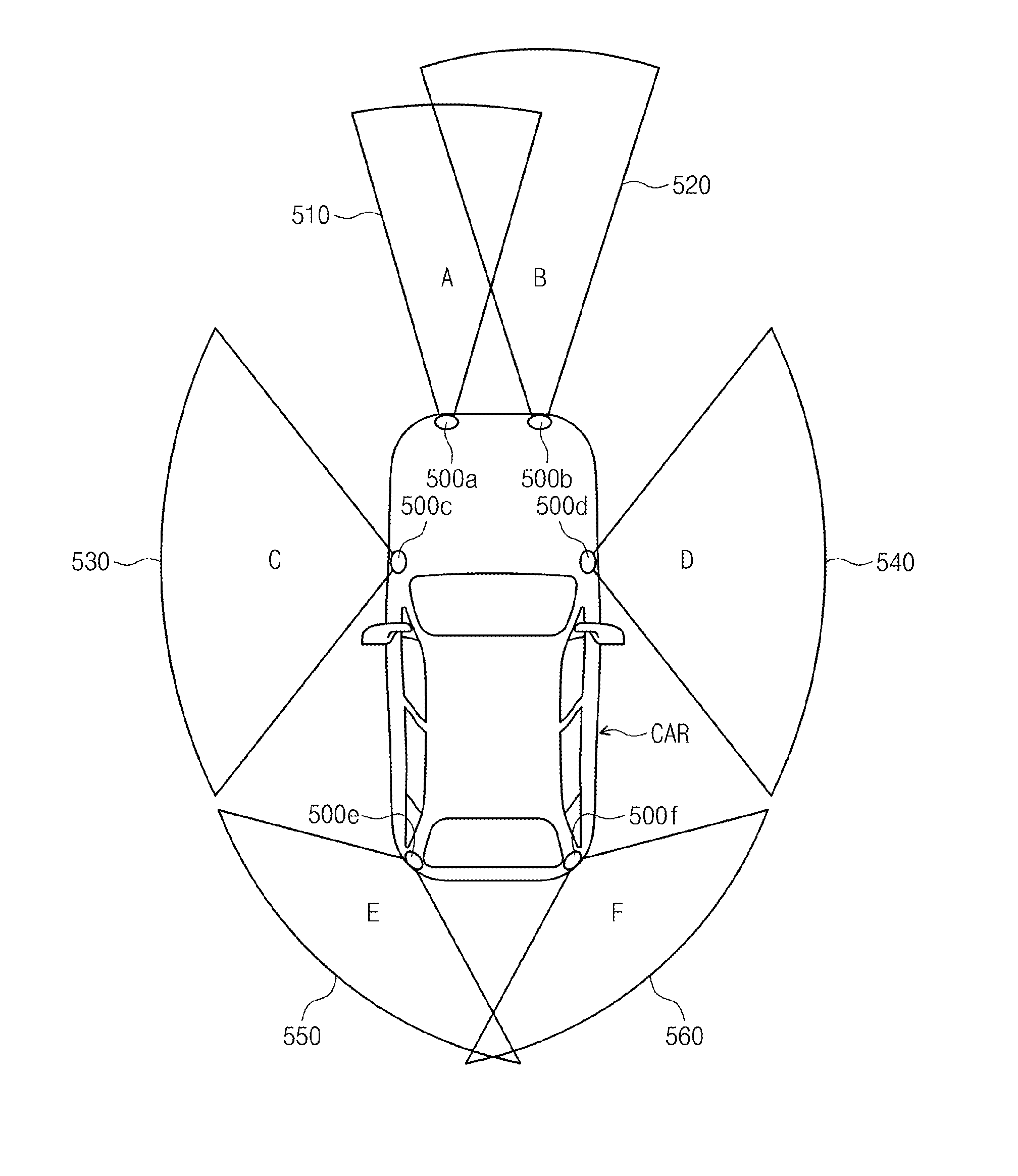
[0094]FIG. 9 shows transmission and reception view ranges configured by a laser radar system according to the present invention. Referring to FIG. 9, a transmission and reception unit 250 includes at least two light transmission units radiating laser pulses (for example an event pulse and an odd pulse) at different times, and a light reception unit. A view range by the laser radar system includes a first transmission view range ROI_TX1 and a second transmission view range ROI_TX2 that are configured by an event shot. The first transmission view range ROI_TX1 is configured by a laser pulse corresponding to the event shot. The first transmission view range ROI_TX1 may be configured to have a relatively wide view angle by a first light transmission unit of the transmission and reception unit 250. The second transmission view range ROI_TX2 is configured by an odd shot radiated by a second light transmission unit of the transmission and reception unit 250. The second transmission view ra...

sixth embodiment

[0102]FIG. 12 shows a laser radar system according to the present invention. Referring to FIG. 12, a laser radar system 300 shows a structure that shares one scanner but may perform optical detection on a plurality of sections.

[0103]A first light source 310 produces an even pulse LE. The even pulse LE produced by the first light source 310 is deflected by an optical deflector and enters an optical splitter 330. One of even pulses LE formed through split by the optical splitter 330 is radiated to a radiation surface corresponding to Section 1. In addition, the other of a plurality of even pulses LE formed through split by the optical splitter 330 is radiated to a region corresponding to Section 3 by a mirror 335. In some cases, the even pulse may also be radiated directly to Section 3 without using the mirror 335 separately.

[0104]Reflected light of the even pulse LE radiated to a target of Section 1 is detected by a first light reception unit 340. In addition, reflected light of the ...


PUM


Abstract

Provided is a laser radar system. The laser radar system includes a first transmission and reception unit sequentially radiating a first laser beam to a plurality of locations within a first view range and receiving a reflected light; and a second transmission and reception unit sequentially radiating a second laser beam to a plurality of locations within a second view range and receiving a reflected light, wherein each of the first transmission and reception unit and the second transmission and reception unit is fixed to a loader and independently searches for the first view range and the second view range.

Description

CROSS-REFERENCE TO RELATED APPLICATIONS[0001]This U.S. non-provisional patent application claims priority under 35 U.S.C. §119 of Korean Patent Application Nos. 10-2013-0076995, filed on Jul. 2, 2013, and 10-2014-0080444, filed on Jun. 30, 2014, the entire contents of which are hereby incorporated by reference.BACKGROUND OF THE INVENTION[0002]The present invention disclosed herein relates to a laser radar, and more particularly, to a laser radar system for obtaining a 3D image.[0003]A 3D image system is used for obtaining image content displayed by a 3D display TV. In addition, the 3D image system may be used for monitoring a long-distance military target or a natural environment such as landslide and for obtaining various 3D images around a car needed for the operation of a manless car.[0004]Even a 3D image having a poor quality may play a role in some regions but with the recent sharp expansion of an application region, various environments need a 3D image having an excellent qual...

Claims


Application Information

Patent Timeline
IPC IPC(8): G01S17/93G01S7/481G01S17/89G01S17/87G01S17/931
CPCG01S17/936G01S7/4817G01S17/89G01S17/87G01S17/931
Inventor MHEEN, BONGKIOH, MYOUNGSOOKSIM, JAE-SIKSONG, JUNG-HOSEO, HONG-SEOKSONG, MINHYUP
Owner ELECTRONICS & TELECOMM RES INST
Why Eureka
Try Eureka