Magnetic recording medium and magnetic storage apparatus

Active Publication Date: 2015-01-08
SHOWA DENKO KK
View PDF6 Cites 6 Cited by
  • Summary
  • Abstract
  • Description
  • Claims
  • Application Information

AI Technical Summary

Benefits of technology

The present invention offers a magnetic recording medium and a magnetic storage apparatus with great signal-to-noise ratios and outstanding writing performance.

Problems solved by technology

Such demands are difficult to satisfy by the method of adding the grain boundary material to the magnetic layer, and the method of providing the soft magnetic underlayer.

Method used


Image

  • Magnetic recording medium and magnetic storage apparatus
  • Magnetic recording medium and magnetic storage apparatus
  • Magnetic recording medium and magnetic storage apparatus

Examples


first embodiment

[0022]A description will be given of a configuration of an example of a magnetic recording medium in this embodiment.

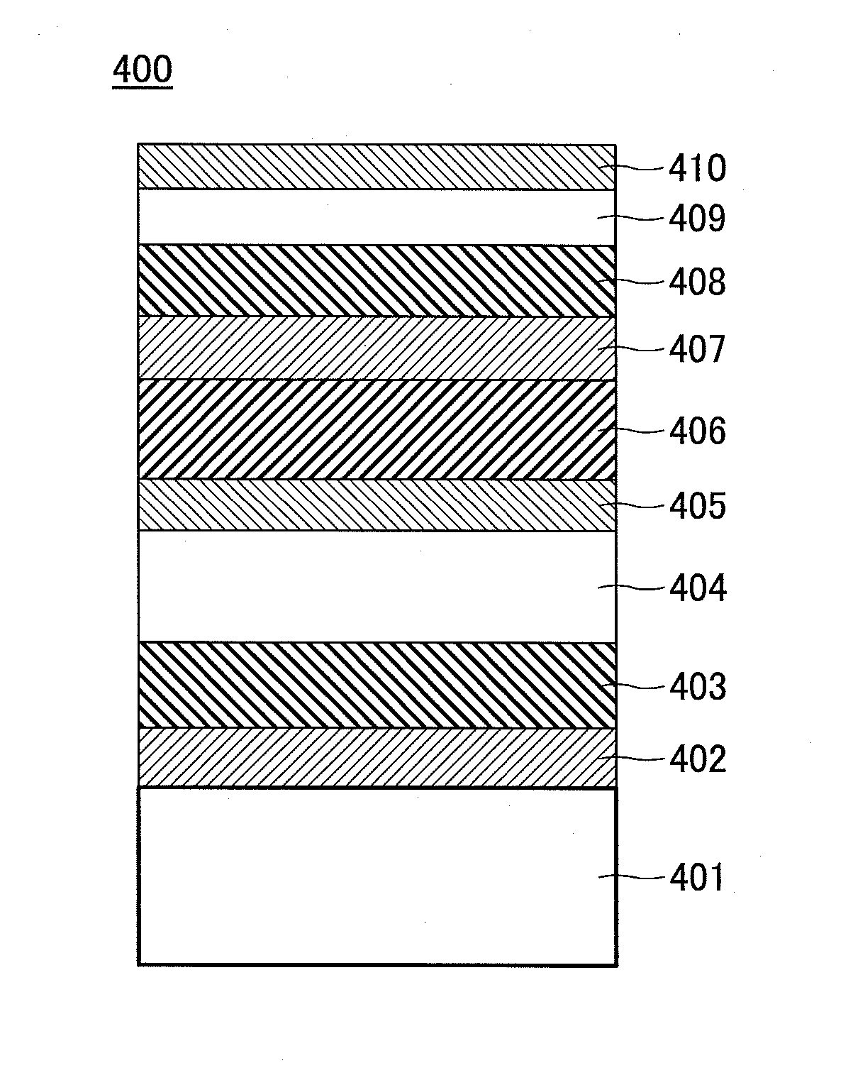
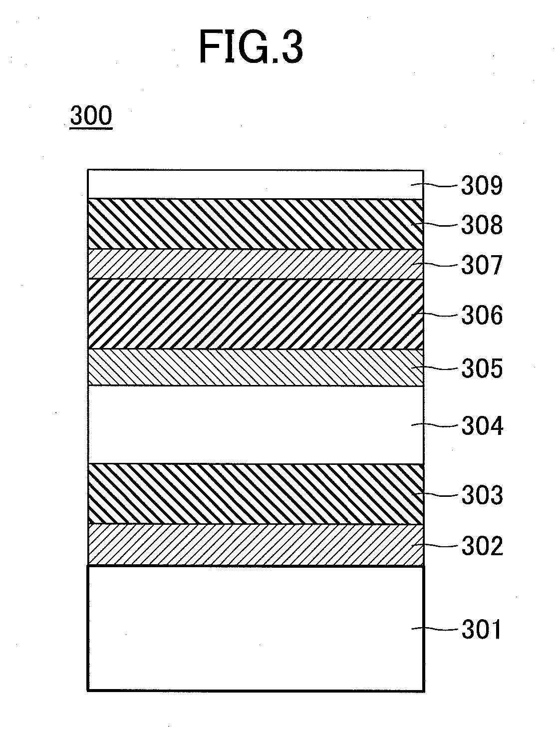
[0023]The magnetic recording medium in this embodiment includes a substrate, a magnetic layer including an alloy having an L10 type crystal structure, and a plurality of underlayers arranged between the substrate and the magnetic layer. Amongst the plurality of underlayers, at least one underlayer may be a soft magnetic underlayer formed by an alloy having an hcp (hexagonal close packed) structure and including Co metal or Co as its main component, with a (11•0) plane oriented parallel to a substrate surface.

[0024]A description will be given of each of the layers of the magnetic recording medium.

[0025]The substrate is not limited to a particular substrate material. For example, a glass substrate, and particularly a heat-resistant glass substrate may be used for the substrate.

[0026]In the magnetic recording medium of this embodiment, the plurality of underlayers are pr...

second embodiment

[0059]Next, a description will be given of an example of a configuration of a magnetic storage apparatus in a second embodiment. In this embodiment, it is assumed for the sake of convenience that the magnetic storage apparatus employs the heat-assisted recording method, however, the recording method employed in the magnetic storage apparatus is not limited to the heat-assisted recording method. The magnetic recording medium in the first embodiment described above may be used in the magnetic storage apparatus employing the microwave-assisted recording method.

[0060]The magnetic storage apparatus in this embodiment may include the magnetic recording medium in the first embodiment described above.

[0061]The magnetic storage apparatus may include, for example, a medium drive unit configured to rotate the magnetic recording medium, and a magnetic head having a near-field light generating element on a tip end part thereof. The magnetic storage apparatus may further include a laser generatin...

example emb3

Practical Example Emb3

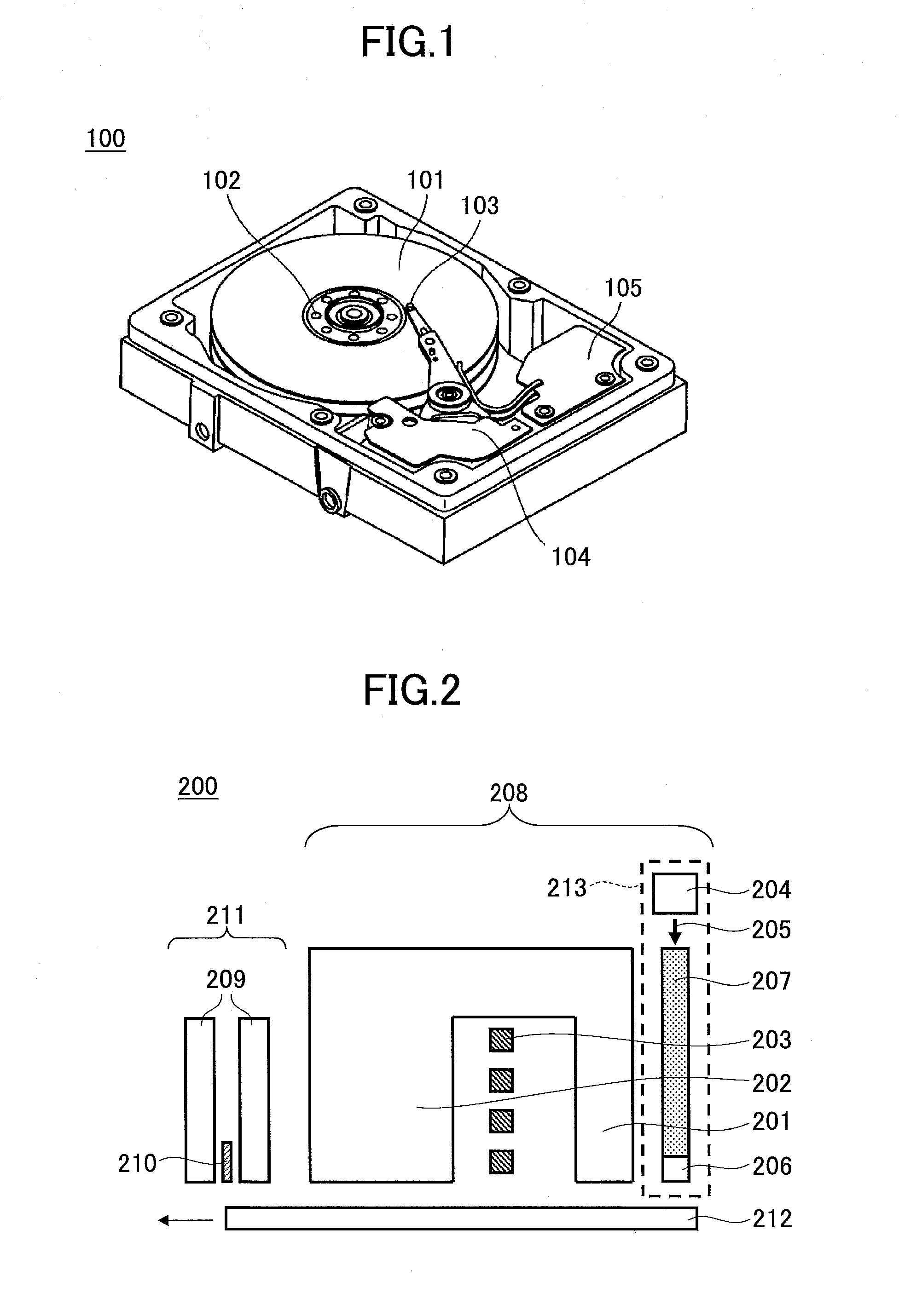
[0089]In practical examples Emb3, the magnetic recording medium in each of the practical examples Emb1.1 through Emb1.10 and the comparison example Cmp1 is assembled within the magnetic storage apparatus 100 illustrated in FIG. 1.

[0090]The magnetic storage apparatus 100 used in the practical examples Emb3 includes the magnetic recording medium 101, the medium drive unit 102 that rotates the magnetic recording medium 101, the magnetic head 103, the head drive unit 104 that moves the magnetic head 103, and the signal processing system 105 that processes signals to be recorded on the magnetic recording medium 101 and signals reproduced from the magnetic recording medium 101 by the magnetic head 103. The heat-assisted recording head 200 illustrated in FIG. 2 and used in the practical examples Emb1 is used for the magnetic head 103.

[0091]Table 3 illustrates a BER (Bit Error Rate) that is evaluated under conditions in which the linear recording density is 1600 kFCI a...


PUM


Abstract

A magnetic recording medium includes a substrate, a magnetic layer including an alloy having an L10 type crystal structure, and a plurality of underlayers arranged between the substrate and the magnetic layer. At least one of the plurality of underlayers is a soft magnetic underlayer formed by an alloy having a hexagonal close packed (hcp) structure and including Co metal or Co as its main component, with a (11•0) plane oriented parallel to a surface of the substrate.

Description

CROSS-REFERENCE TO RELATED APPLICATIONS[0001]This application is based upon and claims the benefit of priority of Japanese Patent Application No. 2013-139825 filed on Jul. 3, 2013, the entire contents of which are incorporated herein by reference.BACKGROUND OF THE INVENTION[0002]1. Field of the Invention[0003]The present invention relates to a magnetic recording medium and a magnetic storage apparatus.[0004]2. Description of the Related Art[0005]Recently, demands to increase storage capacities of HDDs (Hard Disk Drives) are increasing. As one means of satisfying such demands, a heat-assisted recording method and a microwave-assisted recording method have been proposed.[0006]The heat-assisted recording method performs recording with respect to a magnetic recording medium using a magnetic head mounted with a laser light source, by heating the magnetic recording medium by the magnetic head. The microwave-assisted recording method performs recording on the magnetic recording medium by a...

Claims


Application Information

Patent Timeline
IPC IPC(8): G11B5/667G11B20/10G11B5/65
CPCG11B5/667G11B5/653G11B5/656G11B2020/10898G11B2005/0021G11B2005/0024G11B20/10G11B5/314G11B5/82G11B5/7367G11B5/7364G11B5/7363G11B5/657G11B5/658
Inventor KANBE, TETSUYANIWA, KAZUYAMURAKAMI, YUJIZHANG, LEI
Owner SHOWA DENKO KK
Why Eureka
Try Eureka