

Method for mounting a pylon to an aircraft
a technology for aircraft and pylons, which is applied in the direction of metal working apparatus, manufacturing tools, transportation and packaging, etc., can solve the problem of undesirable increase of the space between the wing and the pylon
- Summary
- Abstract
- Description
- Claims
- Application Information
AI Technical Summary
Benefits of technology
Problems solved by technology
Method used
Image

Examples
embodiment 1
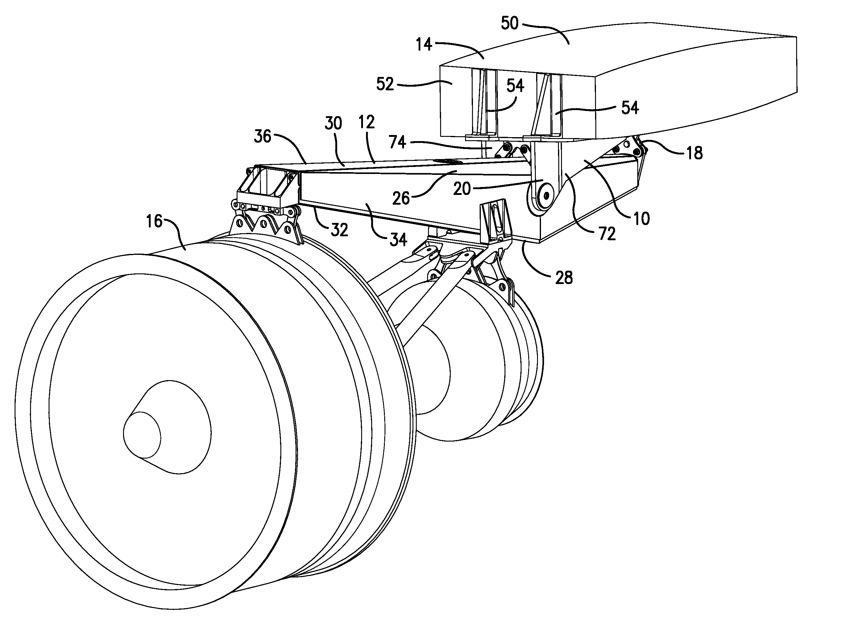
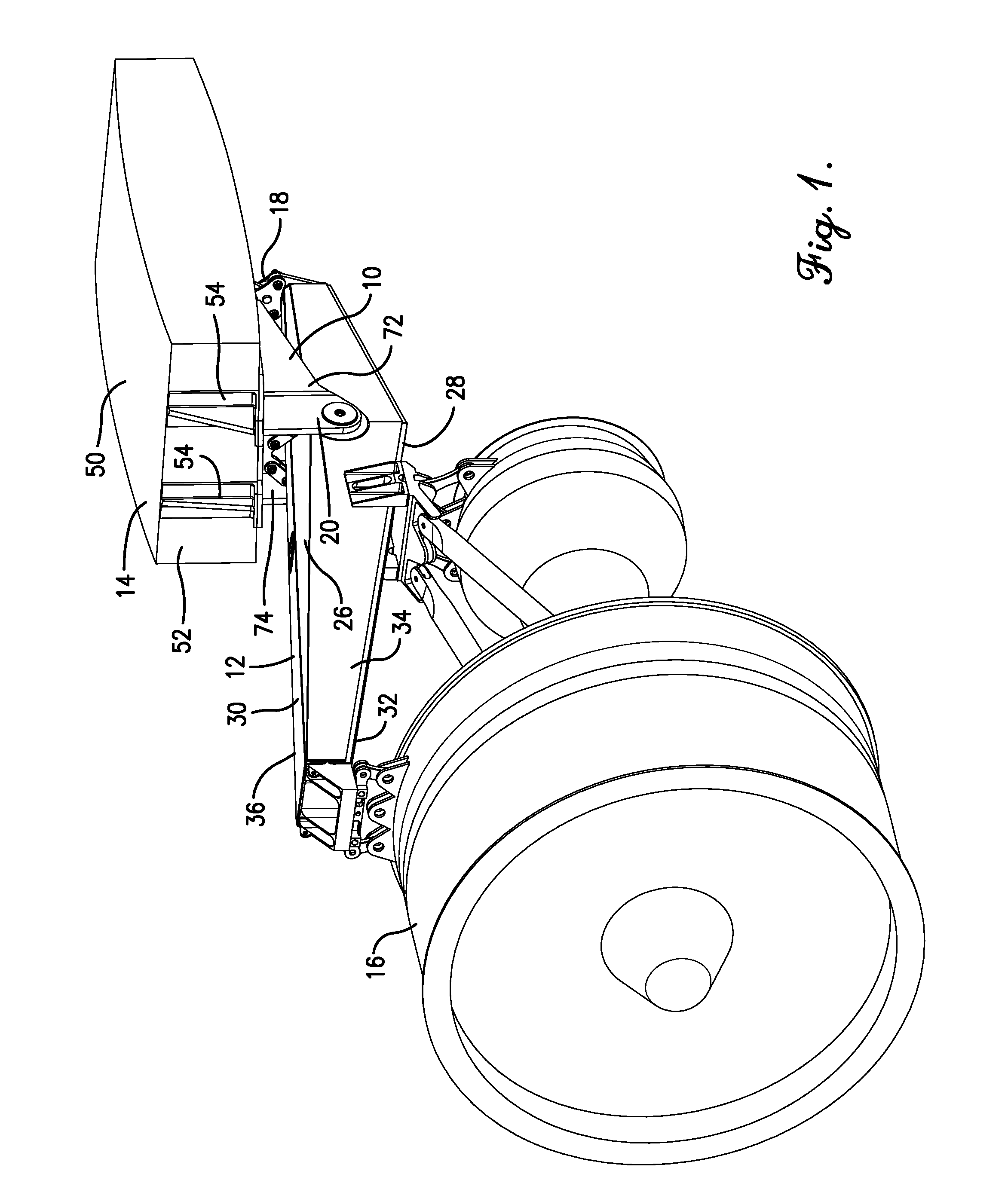
[0026]In a first embodiment of the invention, a method of mounting an engine pylon 12 to a wing 14 of an aircraft may make use of a pylon mounting system 10 as illustrated in FIGS. 1-4. The pylon 12 may support an aircraft engine 16 and / or an engine nacelle, thereby providing the necessary structural load paths and required positioning between the engine 16 and the wing 14. The pylon mounting system 10 may comprise a rear attachment 18 and a forward attachment 20, as well as additional braces and / or structural supports, as described below.
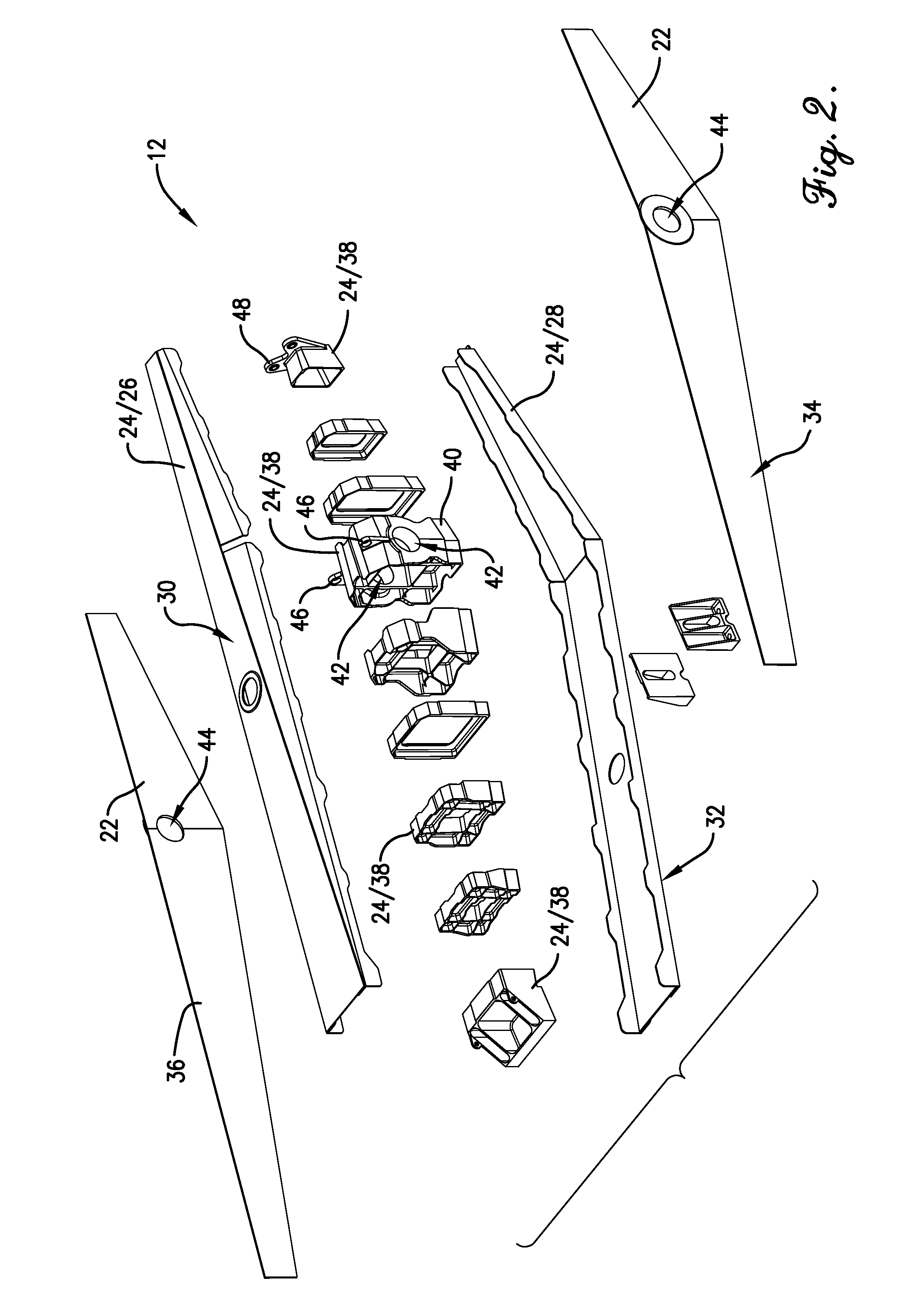
[0027]As illustrated in FIG. 2, the pylon 12 may comprise pylon skin 22, such as composite skin, and frame components 24 to which the pylon skin 22 is formed around and attached to. The frame components 24 may include an upper spar 26 and a lower spar 28. The upper spar 26 may be positioned vertically higher than the lower spar 28. In most embodiments of the invention, the upper spar 26 is positioned closer to the wing 14 than the lower spar 28 and...
embodiment 2
[0044]In a second embodiment of the invention, a method of mounting an engine pylon 212 to a wing (not shown) of an aircraft may make use of a pylon mounting system 210, as illustrated in FIGS. 5 and 6. The pylon mounting system 210 may primarily comprise each of the elements of the pylon mounting system 10 described in the first embodiment of the invention. For example, pylon 212 may be substantially identical to pylon 12, comprising a support bulkhead 240 and corresponding bores 242 formed therethrough, substantially identical to the support bulkhead 40 and bores 42, as well as pylon side holes 244 which may be substantially identical to the pylon side holes 44. Likewise, the pylon mounting system 210 may comprise forward wing-mounted fittings 272,274,276 substantially identical to the forward wing-mounted fittings 72,74,76 of the first embodiment of the invention, including side attachment holes 286 substantially identical to the side attachment holes 86 of the first embodiment o...
embodiment 3
[0046]In a third example embodiment of the invention, a method of mounting an engine pylon 312 to a wing 314 of an aircraft may make use of a pylon mounting system 310, as illustrated in FIGS. 7-9. The pylon mounting system 310 may primarily comprise each of the elements of the pylon mounting system 10 described in the first embodiment of the invention. For example, pylon 312 may be substantially identical to pylon 12, comprising a support bulkhead 340 substantially identical to the support bulkhead 40 and pylon side holes 344 which may be substantially identical to the pylon side holes 44. Likewise, the pylon mounting system 310 may comprise rear and forward attachments 318,320. The forward attachments may likewise comprise forward wing-mounted fittings 372,374,376 substantially identical to the forward wing-mounted fittings 72,74,76 of the first embodiment of the invention, having wing-mounting flanges 384 with side attachment holes 386 formed therethrough. The attachment of the f...
PUM
| Property | Measurement | Unit |
|---|---|---|
| Time | aaaaa | aaaaa |
| Diameter | aaaaa | aaaaa |
| Diameter | aaaaa | aaaaa |
Abstract
Description
Claims
Application Information