Forklift hydraulic control apparatus

a hydraulic control apparatus and forklift technology, applied in the direction of fluid couplings, servomotors, couplings, etc., can solve the problems of complicated configuration of hydraulic control apparatuses, difficult to carry out regenerative operations, and only bringing about insufficient effects of regenerative operations, so as to simplify the configuration of hydraulic control apparatus.

Active Publication Date: 2015-01-15
TOYOTA IND CORP
View PDF2 Cites 13 Cited by
  • Summary
  • Abstract
  • Description
  • Claims
  • Application Information

AI Technical Summary

Benefits of technology

[0017]Accordingly, the present invention simplifies the configuration of the hydraulic control apparatus and ensures effects of regenerative operation.

Problems solved by technology

This complicates the configuration of the hydraulic control apparatus.
However, the regenerative operation is difficult to carry out when the fork is lowered carrying a light load.
As a result, the regenerative operation only brings about insufficient effects.

Method used


Image

  • Forklift hydraulic control apparatus
  • Forklift hydraulic control apparatus
  • Forklift hydraulic control apparatus

Examples


first embodiment

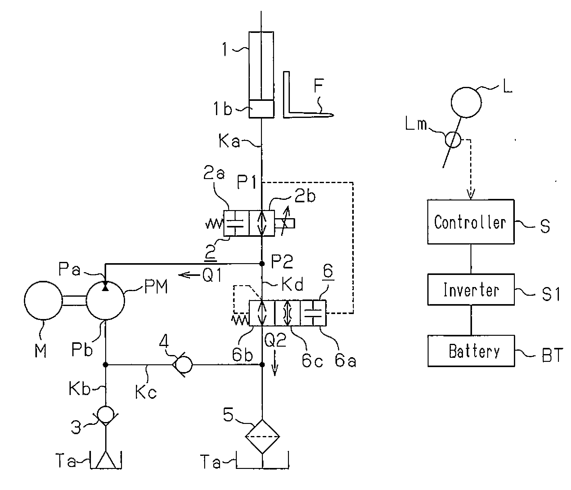
[0027]A first embodiment of the present invention will now be described with reference to FIG. 1.

[0028]A forklift in the first embodiment is a picking forklift having a fork F, which serves as a loading attachment (a loading member) arranged at the front position of the forklift body and is selectively raised and lowered as instructed from the cab. Specifically, the fork F is selectively raised and lowered by means of a lift cylinder 1 serving as a hydraulic lift cylinder selectively extended and retracted through manipulation of a manipulation lever L, which is a raising / lowering manipulation member provided in the cab.

[0029]The hydraulic control apparatus of the first embodiment will hereafter be described.

[0030]The hydraulic control apparatus controls operation of the lift cylinder 1. The hydraulic control apparatus of the first embodiment configures an apparatus that is a hydraulic circuit for operating the lift cylinder 1 with a single pump and a single motor for driving the pu...

second embodiment

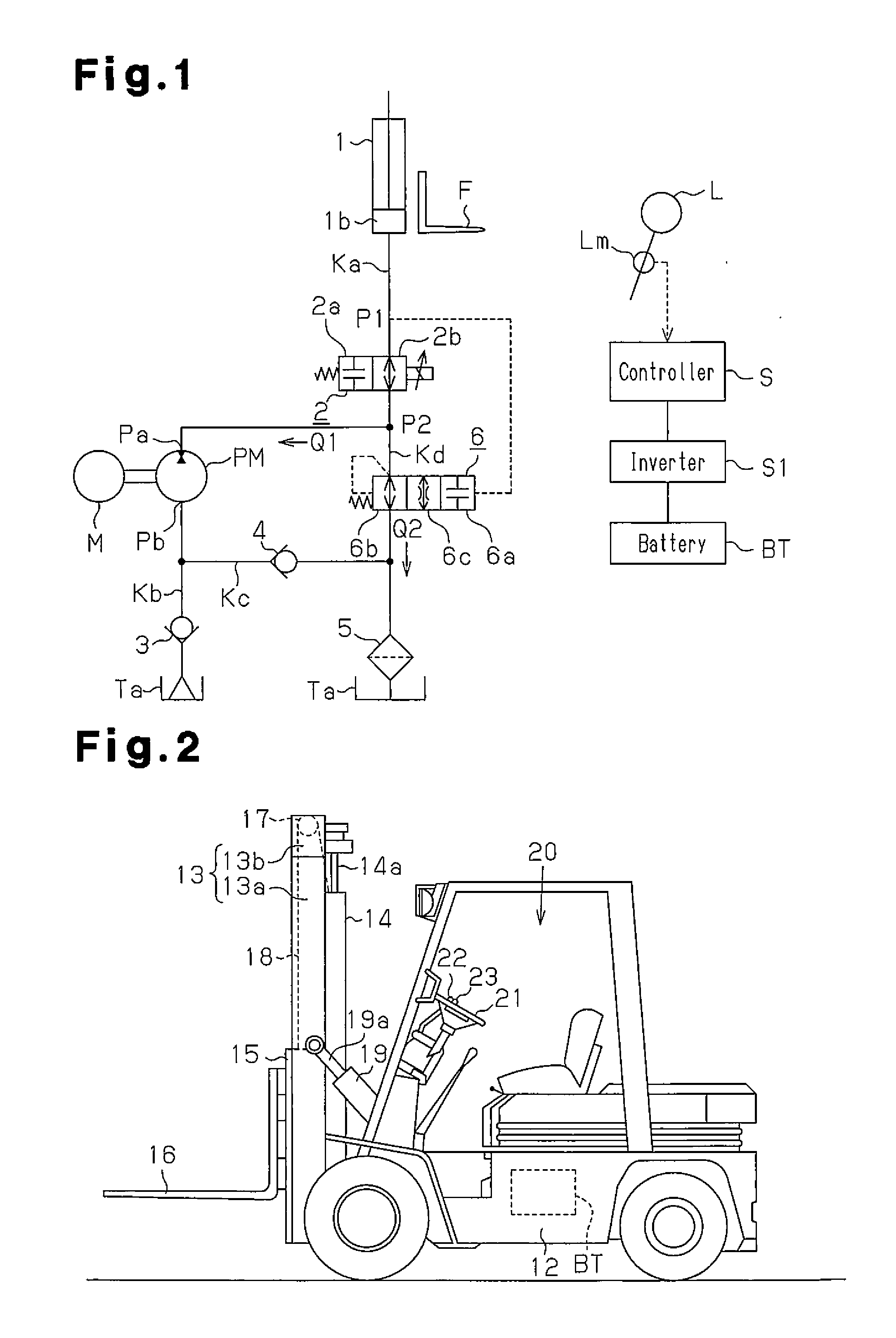
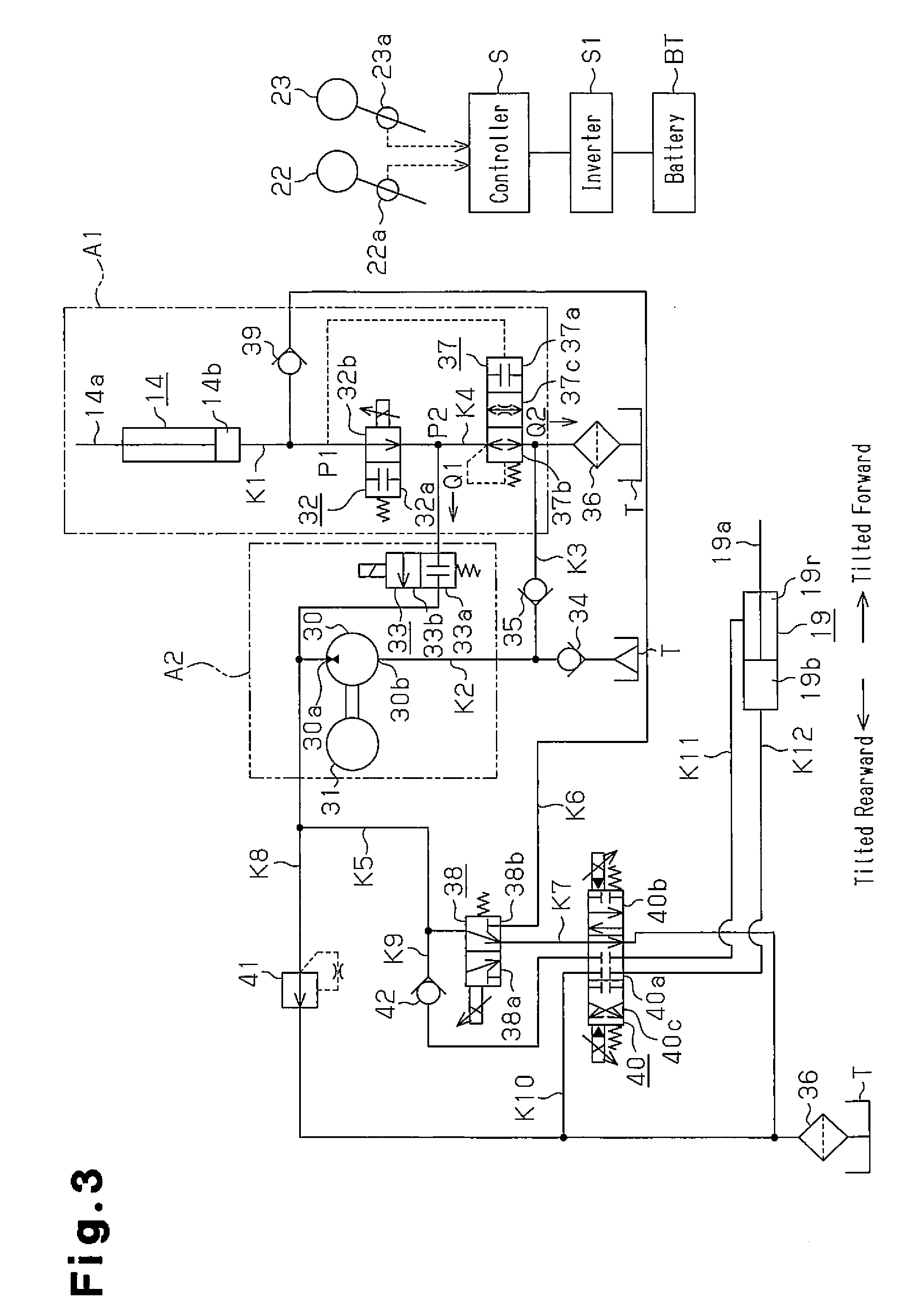
[0058]A second embodiment of the present invention will now be described with reference to FIGS. 2 and 3.

[0059]In the embodiments described below, like or the same reference numerals are given to those components that are like or the same as the corresponding components of the already described embodiment, and overlapped explanations are omitted or simplified.

[0060]A forklift of the second embodiment is a counterbalance forklift. As illustrated in FIG. 2, the forklift includes a mast 13 arranged in a front portion of a body frame 12. The mast 13 includes a pair of, left and right, outer mast portions 13a, which are pivotally supported by the body frame 12, and corresponding inner mast portions 13b, which are mounted on the inner sides of the outer mast portions 13a in an ascendable / descendable manner. A lift cylinder 14 serving as a hydraulic lift cylinder is fixed to the rear side of each of the outer mast portions 13a and extends parallel to the outer mast portion 13a. A piton rod...


PUM


Abstract

An outlet port of a hydraulic pump/motor and a bottom chamber of a lift cylinder are connected to each other by a hydraulic fluid passage. A hydraulic fluid passage that is connected to a hydraulic fluid tank is formed to branch off the hydraulic fluid passage. A flow control valve controls the hydraulic fluid delivered from the lift cylinder when the fork is lowered, thereby regulating the flow rate of hydraulic fluid supplied to the hydraulic pump/motor and the flow rate of hydraulic fluid supplied to the hydraulic fluid tank. If regenerative operation can be performed, the flow control valve is closed and hydraulic fluid is delivered to the hydraulic pump/motor. If regenerative operation cannot be performed, the flow control valve is opened and hydraulic fluid is delivered to the hydraulic fluid tank. In either case, the fork can be lowered at an instructed speed.

Description

CROSS REFERENCE TO RELATED APPLICATIONS[0001]This is a National Stage of International Application No. PCT / JP2013 / 050670 filed Jan. 16, 2013, claiming priority based on Japanese Patent Application No. 2012-021095 filed Feb. 2, 2012, the contents of all of which are incorporated herein by reference in their entirety.BACKGROUND OF THE INVENTION[0002]The present invention relates to a hydraulic control apparatus for a forklift and, more particularly, to a hydraulic control apparatus for controlling a hydraulic cylinder.[0003]A forklift carries out regenerative operation for driving a hydraulic pump / motor as a hydraulic motor by returning hydraulic fluid delivered from a lift cylinder to the hydraulic pump / motor at the time when the fork is lowered (see, for example, Patent Document 1).PRIOR ART DOCUMENTSPatent Documents[0004]Patent Document 1: U.S. Pat. No. 5,649,422SUMMARY OF THE INVENTION[0005]A hydraulic pump / motor includes an inlet port for drawing hydraulic fluid from a fluid tank...

Claims


Application Information

Patent Timeline
Patent Type & Authority Applications(United States)
IPC IPC(8): B66F9/22F15B13/02
CPCF15B13/02B66F9/22F15B11/02F15B21/14F15B2211/20569F15B2211/6336F15B2211/761F15B2211/88
Inventor MATSUO, TSUTOMUISHIKAWA, HIROHIKOUEDA, YUKIGOTO, TETSUYAMORITA, JUNICHI
Owner TOYOTA IND CORP
Why Eureka
Try Eureka