Scissor-type lifting table

a lifting table and scissor-type technology, applied in the direction of lifting frames, lifting devices, etc., can solve the problems of limited possibility of varying the lifting cams used, insufficient maintenance-friendly construction, and difficulty in accessing some areas so as to save costs, hinder the lifting and lowering of the scissor-type lifting table, and avoid the effect of maintenan

Inactive Publication Date: 2015-01-15
MOHR CHRISTOPH
View PDF1 Cites 14 Cited by
  • Summary
  • Abstract
  • Description
  • Claims
  • Application Information

AI Technical Summary

Benefits of technology

[0010]This results in numerous advantages. On the one hand more space is available on the base device for the construction of the lifting cam. Furthermore, in this manner the traction mechanism runs approximately parallel to the base device and no longer extends into the interior of the scissor-type lifting table so that hindrances are largely avoided during maintenance. In addition, in this guidance of the traction mechanism a plurality of deflection devices, in particular deflection

Problems solved by technology

However, due to the limited availability of space the possibilities of varying the lifting cams used are limited.
Furthermore, this construction is not sufficiently maintenance-friendly in a certain sense since the traction bands running inside t

Method used


Image

  • Scissor-type lifting table
  • Scissor-type lifting table

Examples


Embodiment Construction

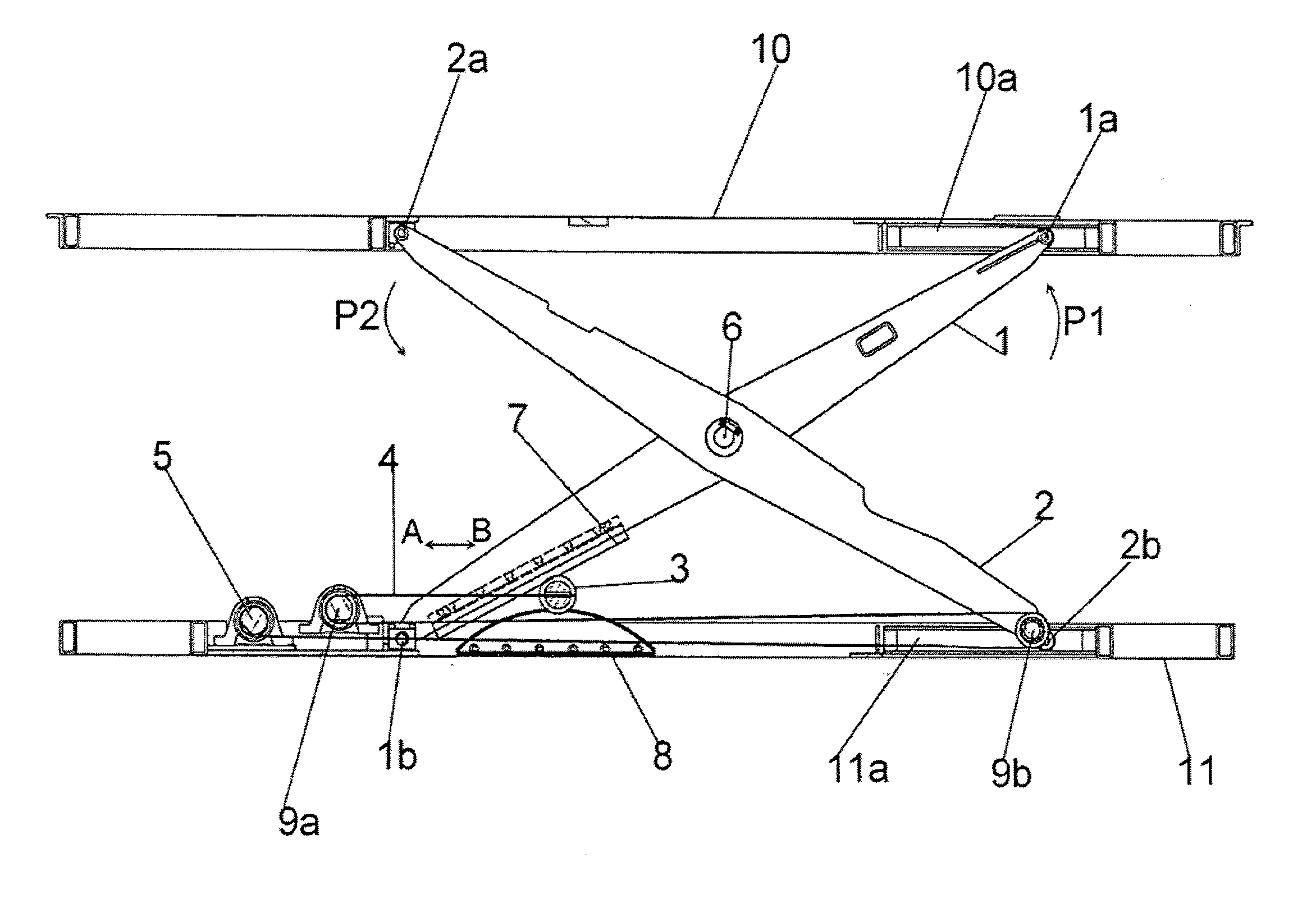
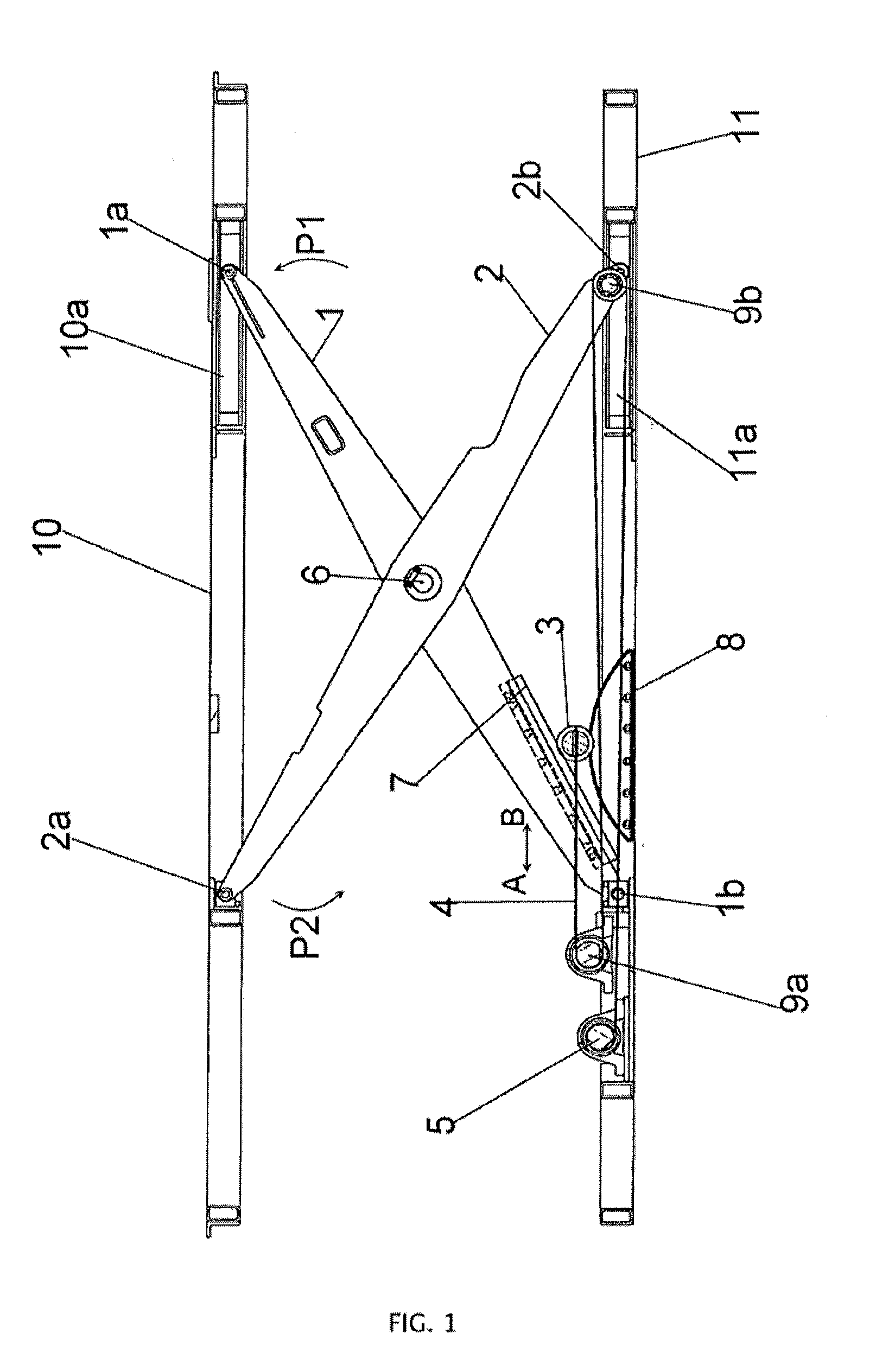
[0014]The scissor-type lifting table is formed by a carrying device 10 for receiving the object to be lifted, a base device 11 to be arranged on the floor or a surface for setting it up and by a scissor mechanism arranged between carrying device 10 and base device 11. The scissor mechanism is formed by crossed scissor blade arrangements, namely, a first scissor blade arrangement 1 and a second scissor blade arrangement 2, that can pivot against one another about a scissor axis 6. Each scissor blade arrangement 1, 2 preferably comprises two or more scissor blades arranged parallel to each other of which only one is represented in the side view shown.

[0015]The scissor blades of a scissor blade arrangement 1, 2 are firmly connected, in particular welded to one another e.g., by cross traverses (not shown).

[0016]As can be seen in the figure, the scissor mechanism is articulated to the second scissor blade arrangement 2 on the carrying device 10. The articulation takes place here with an ...


PUM


Abstract

A scissor-type lifting table has a carrying device (10) and a base device (11). A scissor mechanism comprising first and second scissor-blade arrangements are arranged between the carrying device (10) and the base device (11). The carrying device (10) can be moved away from the base device (11) by means of a lifting truck (3) which can be moved via at least one traction mechanism (4), by winding up of the traction mechanism (4), and can be raised up in order to open the scissor mechanism and can be lowered in order to close the scissor mechanism by unwinding the traction mechanism (4). At least one lifting cam (8) is provided which is configured to regulate the lifting capacity and along which the lifting truck (3) runs during the raising or lowering of the carrying device (10).

Description

TECHNICAL FIELD[0001]The invention relates to a scissor-type lifting table in accordance with the generic part of claim 1.BACKGROUND INFORMATION[0002]A corresponding scissor-type lifting table is known from DE 100 01 910 84. For lifting the table a lifting truck is drawn by a traction band in the direction of the scissor axis between the crossed scissor blades that can pivot about the scissor axis. The lifting truck runs here via lifting cams fastened in a detachable or adjustable manner on the scissor blades. The lifting cams ensure that the lifting load that is applied by the traction band can be distributed over the lifting procedure in an advantageous manner. This facilitates in particular the starting in the completely lowered state of the scissor-type lifting table.[0003]This construction has absolutely proven itself in the past. However, due to the limited availability of space the possibilities of varying the lifting cams used are limited.[0004]Furthermore, this construction...

Claims


Application Information

Patent Timeline
IPC IPC(8): B66F7/06
CPCB66F7/065B66F3/22B66F7/0633B66F7/28
Inventor MOHR, CHRISTOPH
Owner MOHR CHRISTOPH
Why Eureka
Try Eureka