
Charger, Battery Pack Charging System and Cordless Power Tool System

a charging system and battery pack technology, applied in the direction of charging devices, charging exchange data, manufacturing tools, etc., can solve the problems of battery pack not being charged, user cannot perform the scheduled work, charging operation will not begin, etc., to achieve convenient use and reliably charge

Active Publication Date: 2015-01-15
MAKITA CORP
View PDF3 Cites 30 Cited by
  • Summary
  • Abstract
  • Description
  • Claims
  • Application Information

AI Technical Summary

Benefits of technology

[0007]It is therefore an object of the present teachings to provide techniques for charging battery packs that reduce the possibility of human error.
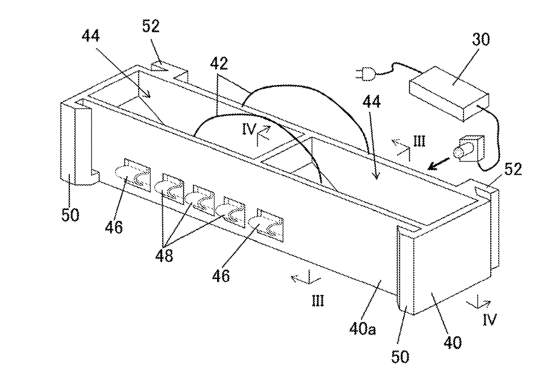
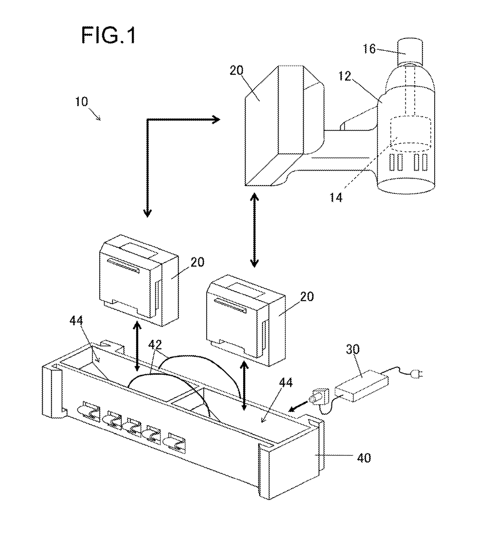
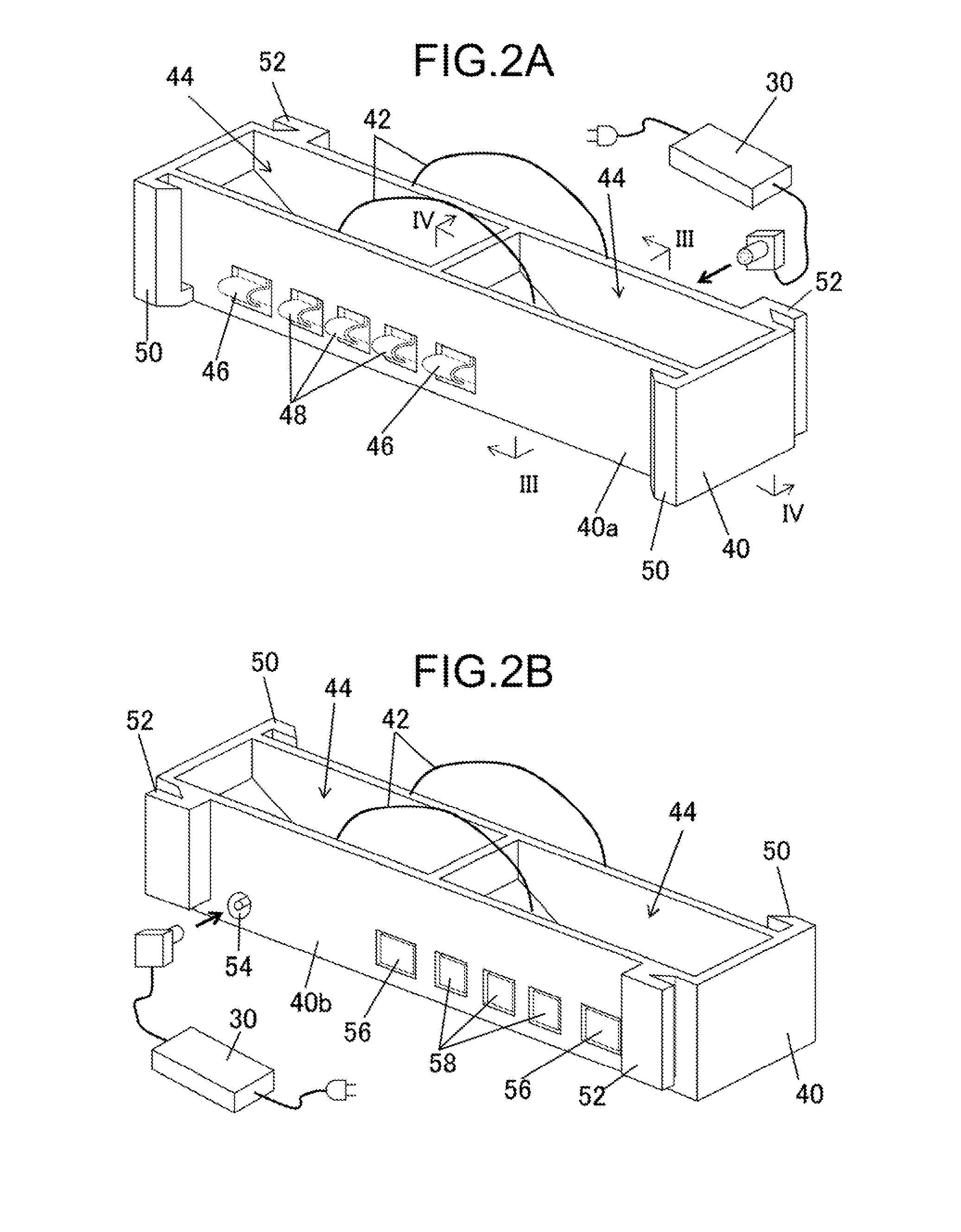
[0010]In chargers according to the present teachings, the cross sectional area of the battery pack housing hole is relatively large at an upper part thereof and smaller at a lower part thereof. Because the upper opening area of the battery pack housing hole is relatively large, the battery pack can be easily put into the battery pack housing hole and the user does not have to pay careful attention to the placement of the battery pack within the battery pack housing hole. But, since the cross sectional area inside the battery pack housing hole decreases or tapers in the downward direction, the battery pack that has been put into the battery pack housing hole will reliably move (slide) toward the prescribed position due to its own weight (gravity) while being guided by one or more side walls of the battery pack housing hole. When the battery pack has moved to the prescribed position (e.g., a lowermost position of the battery pack within the battery pack housing hole), the charging output part will automatically begin transmitting (wirelessly or by conducting current via a wire) charging power to the battery pack. According to this system, the battery pack can be reliably charged even if the user puts the battery pack into the battery pack housing hole in a rough or careless manner, i.e. without paying special attention to the location of charging terminals or a charging output power element within the battery pack housing hole.

Problems solved by technology

On the other hand, if the battery pack is not properly attached to the charger, the charging operation will not begin.
Therefore, many users have experienced the frustrating situation in which, just as the user is about to use the power tool, the user unexpectedly finds that the battery pack has not been charged because the battery pack was not correctly attached to the charger.
During that interval, the user cannot perform his or her scheduled work.

Method used


Image

  • Charger, Battery Pack Charging System and Cordless Power Tool System
  • Charger, Battery Pack Charging System and Cordless Power Tool System
  • Charger, Battery Pack Charging System and Cordless Power Tool System

Examples


first embodiment

[0026]A first representative, non-limiting embodiment of a power tool system 10 according to the present teachings will now be explained with reference to FIGS. 1-6. This power tool system 10 comprises a hand-held power tool 12, battery packs 20, and a charger 40. The power tool 12 comprises a motor 14, which drives a tool 16, e.g., a tool bit coupled to the motor 14 via a chuck. While the motor 14 is preferably an electrically-driven, rotary motor, it may instead be a solenoid or some other electric actuator. The battery packs 20 serve as power supplies for the power tool 12 and supply electric current (power) to the motor 14. The battery packs 20 can be attached to and detached from the power tool 12. The battery packs 20 have a plurality of secondary batteries (e.g., lithium ion cells) built in (housed therein) and are rechargeable. The battery packs 20, once they have been detached from the power tool 12, can be attached to and detached from the charger 40, or as further explain...

second embodiment

[0046]A power tool system 210 according to a second embodiment of the present teachings will be explained with reference to FIG. 7, in which the same reference numbers will be utilized for the same elements / components as the preceding embodiment, such that it is not necessary to repeat the description of such elements / components.

[0047]The system 210 of the present embodiment comprises the hand-held power tool 12, the battery packs 20, a tray shaped charger 240, a carrying case 200, and a rapid charger 280. In this embodiment, engaging parts 250, which are adapted or configured physically (mechanically) couple or engage with corresponding rear side engaging parts on the charger 240, are provided on the side surface 200a of the carrying case 200. Therefore, the tray shaped charger 240 can be attached to and detached from the side surface 200a of the carrying case 200, thereby saving space inside of the carrying case 200.

[0048]The tray shaped charger 240 comprises two battery pack hous...

third embodiment

[0049]A charger 340 according to a third embodiment of the present teachings will be explained with reference to FIGS. 8 and 9. The charger 340 of the third embodiment differs from the charger 40 of the first embodiment in that the charger 340 uses a contact type terminal as a charging output part 362. That is, charging current is conducted from the charger 60 to the battery pack 20 via a wired connection. The charging output part 362 thus preferably includes contact terminals adapted or configured to contact and electrically connect to corresponding contact terminals on the battery pack 20. For example, the contact terminals of the battery pack 20 and the charging output part 362 may be designed in the same manner as known power tool charging configurations.

[0050]The remaining structures, elements and components of the third embodiment may be substantially the same as those of the charger 40 of the first embodiment.

[0051]With respect to all of the disclosed aspects and embodiments ...


PUM


Abstract

A charger (40; 240; 340) charges a battery pack (20) that is detachably attachable to a cordless power tool (12). The charger has at least a first side wall (44b) that at least partially defines a battery pack receiving hole (44; 244) shaped to receive and accommodate the battery pack. A charging output element (62; 362) supplies charging power to the battery pack. The battery pack receiving hole has a lateral cross sectional area that decreases downwardly in the vertical direction of the battery pack receiving hole such that gravity causes the battery pack to be guided to a prescribed position within the battery pack receiving hole. In addition, the charging output element is positioned so as to be proximal to a corresponding charging power input element of the battery pack when the battery pack is disposed in the prescribed position.

Description

CROSS-REFERENCE[0001]The present application claims priority to U.S. provisional patent application Ser. No. 61 / 581,943 filed on Dec. 30, 2011 and U.S. provisional patent application Ser. No. 61 / 702,559 filed on Sep. 18, 2012, the contents of both of which are incorporated fully herein.TECHNICAL FIELD[0002]The present invention generally relates to a charger for charging a battery pack that is detachably attachable to a cordless power tool, to a battery pack charging system containing the same and to a cordless power tool system containing the same.BACKGROUND ART[0003]A cordless power tool system is disclosed in WO2006 / 044693A2. This system comprises a power tool, a battery pack, which can be attached to and detached from the power tool, and a charger, which charges the battery pack.[0004]With such a cordless power tool, an external power supply (e.g., an electrical outlet) is not needed to operate the power tool. Instead, the user needs to charge the battery pack beforehand. The ba...

Claims


Application Information

Patent Timeline
Patent Type & Authority Applications(United States)
IPC IPC(8): H02J7/00
CPCH02J7/0045H02J7/02B25H3/022H02J7/0013H02J50/80H02J2310/22H02J50/40H02J50/10H02J5/00H02J7/00034H02J7/00045H02J7/0044
Inventor ITO, KOSUKESUZUKI, HITOSHINAITO, AKIRA
Owner MAKITA CORP
Learn More