Passive arc protection for main breaker line side power conductors

a technology of power conductors and main breaker lines, applied in the direction of switchgear details, emergency protective circuit arrangements, switchgear arrangements, etc., can solve the problems of unrecognized system failures, inconvenience trips, and no one of the above passive methods can limit fault duration, so as to reduce the chance of occurrence, reduce the intensity and duration, and the effect of dramatic benefits for safety and equipment reliability

Active Publication Date: 2015-01-15
SCHNEIDER ELECTRIC USA INC
View PDF16 Cites 22 Cited by
  • Summary
  • Abstract
  • Description
  • Claims
  • Application Information

AI Technical Summary

Benefits of technology

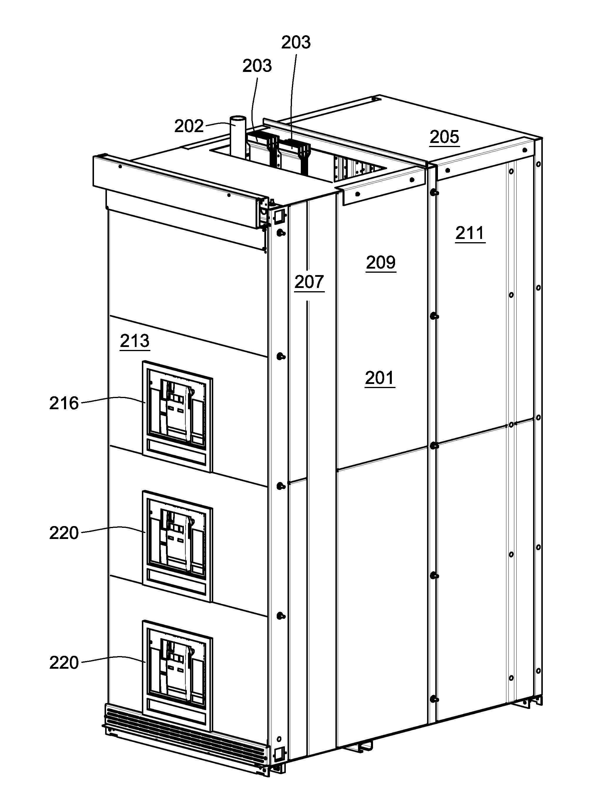
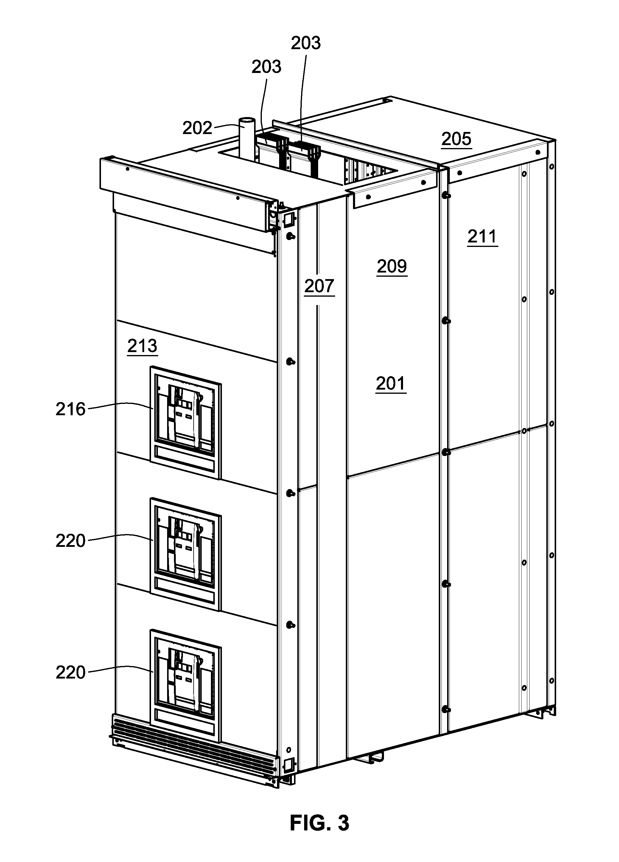
[0013]A quick, economical, passive mechanism for controlling and extinguishing arc events inside electrical cabinets would be welcome in the art. To that end, the present invention in its various aspects and embodiments teaches and provides an arc management system having arc-controlling surrounds for the conductors. One portion of the arc-controlling surrounds forms generally tubular “arc channels,” surrounding uninsulated joints of the incoming power conductors to channel and control arc faults. One end of the arc channels may be joined to conduits surrounding further extensions of the conductors. Another end of the arc channels may terminate in a plenum, which can form a geometry and act as a chamber to hold the attenuated arc until it is extinguished. Since the arc-controlling structures can be considered as basically tubular, terminology common to curved surfaces may be used herein as an aid to explanation. The arc channel will lengthen the nascent arc and together with the associated plenum, if needed, attenuate the current and temperature until preferably the arc is extinguished. The arc channels and associated conduits can further provide barriers against unwanted solid conductor formation / infiltration.
[0014]Thus several advantages may be provided by the arc management system including arc prevention by physical barrier to inadvertent entry of shorting conductors such as dropped tools or vermin; and arc channeling with extinguishing or attenuation by the arc channels and associated exhaust channels which are sized, located and arranged so as to draw out and cool the arc thereby lessening its current and heat with attendant equipment and safety benefits.
[0019]The present invention uses passive arc attenuation and extinguishing technology similar to that previously described in Applicants' [CRC-0266 AND CRC-0275]), for controlling the arc faults and shall be referred to sometimes herein for simplicity as “arc block” technology or structure. The arc block technology of the present invention will be located above, i.e. upstream of, the main breaker of the switchgear cabinet around the uninsulated joints of the incoming conductors. The arc block technology at this location may provide dramatic benefits in safety and equipment reliability by reducing the chance of occurrence of an arc flash for these upstream conductors and reducing the intensity and duration of any arc flashes that do occur by choking the arc of its energy to achieve attenuation or extinguishment.
[0020]The extension of this passive arc block technology electrically upstream of the power connections to the Main Breaker, wherever it is physically located in the cabinet, may have several key benefits:1. The arc block operates in a manner completely independent of the remote upstream device and is unaffected by its performance settings. The arc block will clear the fault regardless of the remote upstream device breaker settings or even if it fails to operate.2. The arc in the equipment can be passively extinguished, leaving the main circuit breaker untripped, and the downstream loads on-line, thus enhancing electrical system reliability.3. The Incident Energy rating of the arc block will be known beforehand across all operating voltages and short circuit currents and can be labeled directly from the factory. Thus, the need for an on-site arc flash study could be avoided.4. Because the energy coming into the cabinet is now controlled by the arc block apparatus, the upper limit of arc flash energy available in the cabinet becomes a function of the main circuit breaker settings and the PPE can be adjusted accordingly.5. An internal arcing fault which starts downstream of the main breaker cannot transfer to the line side conductors above the main circuit breaker because an arc block structure will provide a physical barrier to prevent the transfer.
[0021]Further, flow-through ventilation with exhaust channels can be integrated into the arc block systems for the equipment, the operation of the distribution gear can be cooler, resulting in better performance with less material expenditure. By combining arc management structure and ventilation structure, the benefits of both may be combined and utilized within the typically confined spaces of electrical enclosures. The arc block structure of the present invention can further be integrated with additional arc block structures located according to Applicants' previous teachings, i.e. at the backplane of the breakers, to achieve greater arc control.

Problems solved by technology

Neither of the above passive methods limits fault duration.
Concerns with active means may include expense, nuisance trips, speed, and undetected system failures.
The problem is then of course that several branches, i.e. locations, may have their power interrupted by this action when the arc is only occurring at one location, i.e. branch.
This is the selectivity problem.

Method used


Image

  • Passive arc protection for main breaker line side power conductors
  • Passive arc protection for main breaker line side power conductors
  • Passive arc protection for main breaker line side power conductors

Examples


Embodiment Construction

[0032]As an initial matter, it will be appreciated that the development of an actual, real commercial application incorporating aspects of the disclosed embodiments will require many implementation specific decisions to achieve the developer's ultimate goal for the commercial embodiment. Such implementation specific decisions may include, and likely are not limited to, compliance with system related, business related, government related and other constraints, which may vary by specific implementation, location and from time to time. While a developer's efforts might be complex and time consuming in an absolute sense, such efforts would nevertheless be a routine undertaking for those of skill in this art having the benefit of this disclosure.

[0033]It should also be understood that the embodiments disclosed and taught herein are susceptible to numerous and various modifications and alternative forms. Thus, the use of a singular term, such as, but not limited to, “a” and the like, is n...


PUM


Abstract

In a switchgear cabinet, the line side power conductors upstream of the main breaker are surrounded with are attenuating / extinguishing channels and protective conduit in a location prior to the conductor's attachment to the main breaker. Thus, passive arc attenuation can be had prior to the breakers, Personal Protection Equipment (PPE) levels can be predicted and controlled, and the need for action by circuit breakers during an arcing event is substantially lessened.

Description

[0001]This Application claims priority to prior applications CRC-0266 [US filed 20 Apr. 2012] 13 / 452,145 and CRC-0275 [WO filed 17 Jul. 2013] PCT / US13 / 50797.BACKGROUND OF THE INVENTION[0002]1. Field Of The Invention[0003]The present invention relates generally to electrical distribution equipment and conductors contained within enclosures referred to herein generally as cabinets, although such enclosures need not have doors to benefit from the present invention. The invention relates more particularly to passively preventing, and controlling the effects of, unintended arc faults in electrical cabinets by use of a tunneled arc extinguisher system for an electrical enclosure on the incoming power conductors.[0004]2. Discussion of the Related Art[0005]The hazards of unexpected and / or uncontrolled arcing events, i.e. electrical discharge through a gas, also called arc faults, in an electrical cabinet are well known and include potential damage to equipment and harm to personnel in the o...

Claims


Application Information

Patent Timeline
Patent Type & Authority Applications(United States)
IPC IPC(8): H01H9/34H02B11/04
CPCH01H9/342H01H9/34H02B11/04H02B1/56H02B13/025H02B1/20
Inventor FABER, TIMOTHY R.WOODSON, CAMERON L.
Owner SCHNEIDER ELECTRIC USA INC
Why Eureka
Try Eureka