Non-invasive intracranial pressure monitoring system and method thereof

a monitoring system and intracranial pressure technology, applied in the field of non-invasive intracranial pressure monitoring system, can solve the problems of inability to image every soldier or athlete in the field, inconvenient operation, and large power consumption of most conventional imaging methods

Active Publication Date: 2015-01-15
VIVONICS
View PDF1 Cites 5 Cited by
  • Summary
  • Abstract
  • Description
  • Claims
  • Application Information

AI Technical Summary

Problems solved by technology

A closed-head brain injury, whether incurred as a result of blunt force trauma or a blast wave, can have insidious effects on a person.
Although many casualties may suffer from headache or dizziness, it is difficult with conventional systems and methods to image every soldier or athlete in the field who experiences a potential brain injury.
Most conventional imaging methods are large and require significant power.
Moreover, damage to delicate brain tissues is frequently undetectable by conventional imaging, including CT scanning, even when such imaging is available.
Damage to the small structures within a brain cause local swelling and cerebral blood flow and systemic blood pressure may not necessarily decrease with brain swelling.
Therefore, even mild swelling of about 1 to 3 cc of extra fluid results in increased pressure.
This elevated intracranial pressure (ICP) can itself cause more damage, including brain cell death and permanent brain injury or death.
However, an unknown percentage of these injured are experiencing clinically significant elevated ICP which may worsen or result in permanent damage which could otherwise be avoided with the appropriate application of pharmacological or surgical interventions.
Currently, there is no known robust, portable, and reliable system or method which can accurately monitor ICP without direct access to the intracranial space.
Therefore, it may not be feasible to check ICP on every person who has or may have experienced trauma to the brain.
However, such conventional systems may only provide information based on an empirical diagnostic technique which may not take into account individual variability with regards to susceptibility of brain injury.
Thus, two people experiencing the same physical trauma are likely to exhibit different levels of damage, but without a direct measure of the damage, they may be impossible to differentiate.
These conventional systems and methods often employ large, heavy, power intensive equipment, such as MRI, and the like, and therefore are not portable.
This limits their use in the battlefield or at the sidelines in sports related injuries.
However, as disclosed therein, only two sensors are used which may limit the accuracy of the measured ICP.
Moreover, to date no practical device has emerged from the '656 patent application.

Method used


Image

  • Non-invasive intracranial pressure monitoring system and method thereof
  • Non-invasive intracranial pressure monitoring system and method thereof
  • Non-invasive intracranial pressure monitoring system and method thereof

Examples


Embodiment Construction

[0032]Aside from the preferred embodiment or embodiments disclosed below, this invention is capable of other embodiments and of being practiced or being carried out in various ways. Thus, it is to be understood that the invention is not limited in its application to the details of construction and the arrangements of components set forth in the following description or illustrated in the drawings. If only one embodiment is described herein, the claims hereof are not to be limited to that embodiment. Moreover, the claims hereof are not to be read restrictively unless there is clear and convincing evidence manifesting a certain exclusion, restriction, or disclaimer.

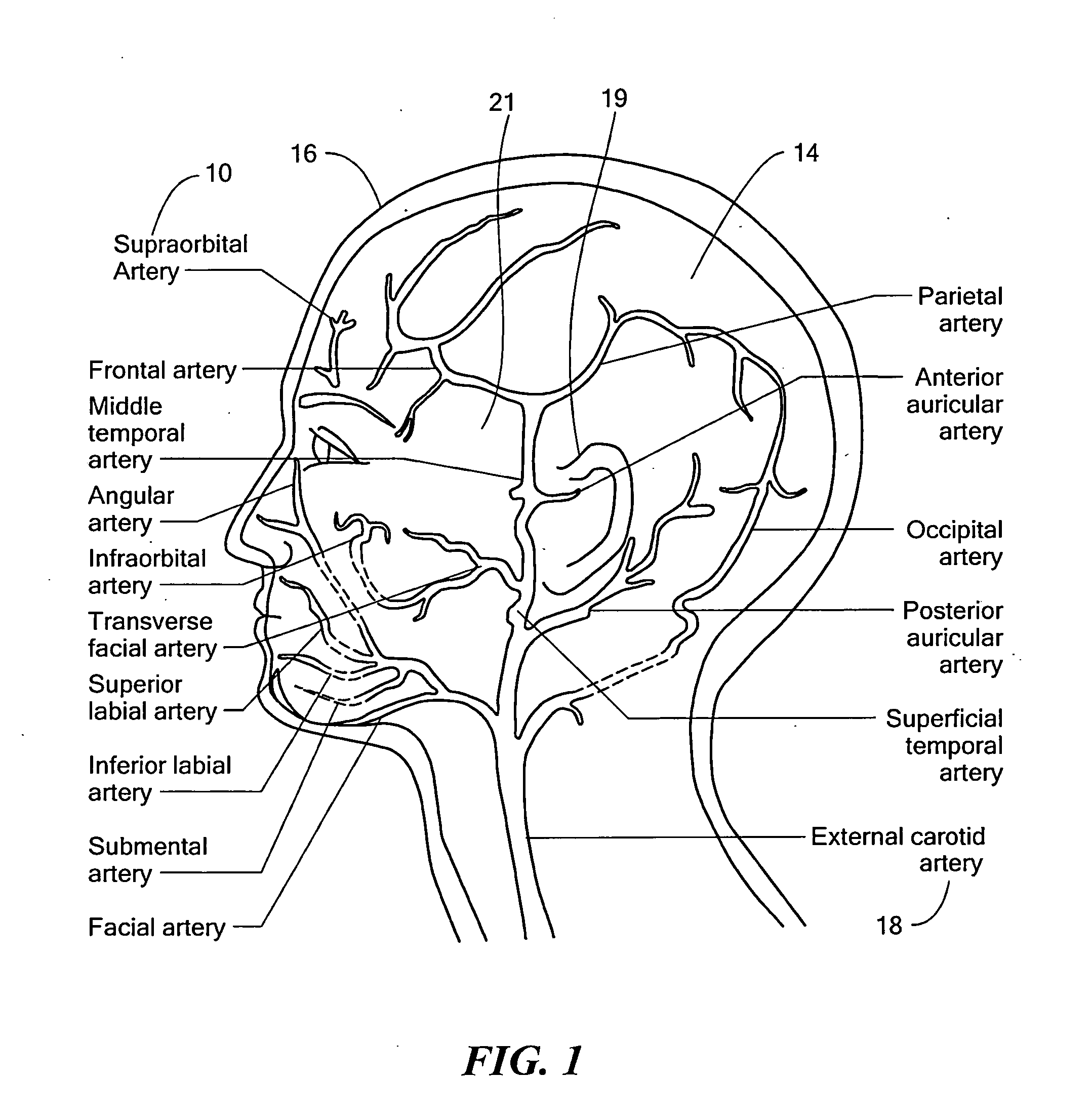
[0033]FIG. 1 shows an example of the vasculature of the human head. One key vasculature often used in determining ICP is supraorbital artery 10. Supraorbital artery 10 is an example of an artery which receives a flow of blood which emanates from within cranial cavity 14. As can be seen, supraorbital artery 10 is proximate f...


PUM


Abstract

A system which includes a first sensor placed proximate to a perfusion field of an artery receiving blood which emanates from the cranial cavity is configured to monitor pulsations of the artery receiving blood which emanates from the cranial cavity artery. A second sensor placed proximate to a perfusion field of an artery which does not receive blood emanating from the cranial cavity and approximately the same distance from the heart as the first sensor configured to monitor pulsations of the artery which does not receive blood emanating from the cranial cavity. A third sensor placed distally from a heart is configured to monitor pulsations of a distal artery. A processing system responsive to signals from the first, second, and third sensors is configured to determine intracranial pressure.

Description

GOVERNMENT RIGHTS[0001]This invention was made with U.S. Government support under Contract No. N68335-10-C-0079, awarded by the Navy, and W81XWH-09-C-0118, awarded by the Army. The Government may have certain rights in certain aspects of the subject invention.FIELD OF THE INVENTION[0002]This invention relates to a non-invasive intracranial pressure monitoring system and method thereof.BACKGROUND OF THE INVENTION[0003]A closed-head brain injury, whether incurred as a result of blunt force trauma or a blast wave, can have insidious effects on a person. Although many casualties may suffer from headache or dizziness, it is difficult with conventional systems and methods to image every soldier or athlete in the field who experiences a potential brain injury. Most conventional imaging methods are large and require significant power. Moreover, damage to delicate brain tissues is frequently undetectable by conventional imaging, including CT scanning, even when such imaging is available.[000...

Claims


Application Information

Patent Timeline
Patent Type & Authority Applications(United States)
IPC IPC(8): A61B5/00A61B5/03A61B5/024
CPCA61B5/7246A61B5/7278A61B5/031A61B5/6824A61B5/6826A61B5/02438A61B5/6815A61B5/742A61B5/6814A61B5/6825
Inventor GALEA, ANNA M.
Owner VIVONICS
Why Eureka
Try Eureka