Control Groups for Network Testing

a network connection and control group technology, applied in the field of network connection performance testing, can solve problems such as man-made disasters, inefficient routing protocols, failures or reductions along any number of “paths” between a source (e.g., a website server) and a user device,

Active Publication Date: 2015-01-15
CENTURYLINK INTPROP
View PDF13 Cites 19 Cited by
  • Summary
  • Abstract
  • Description
  • Claims
  • Application Information

AI Technical Summary

Benefits of technology

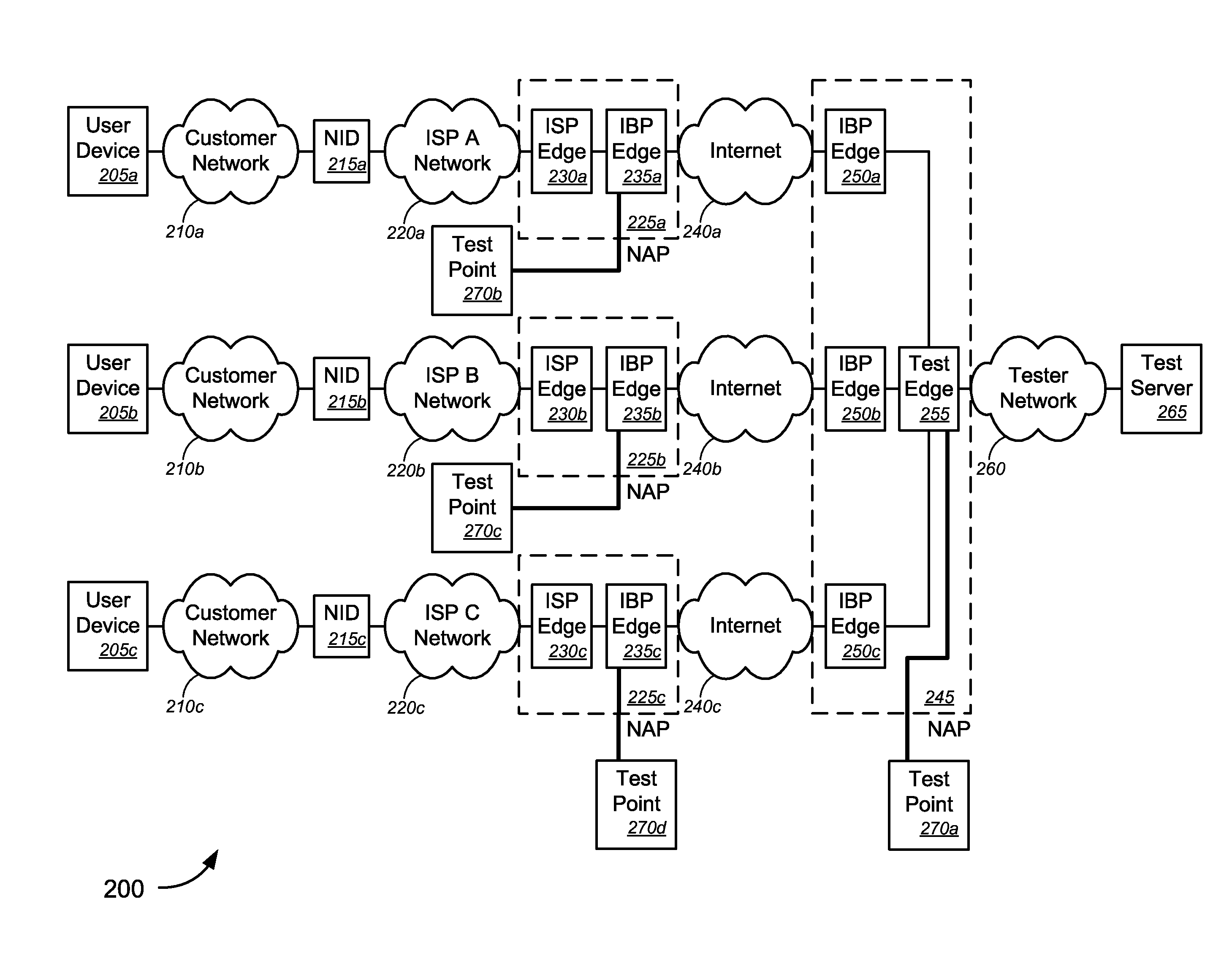
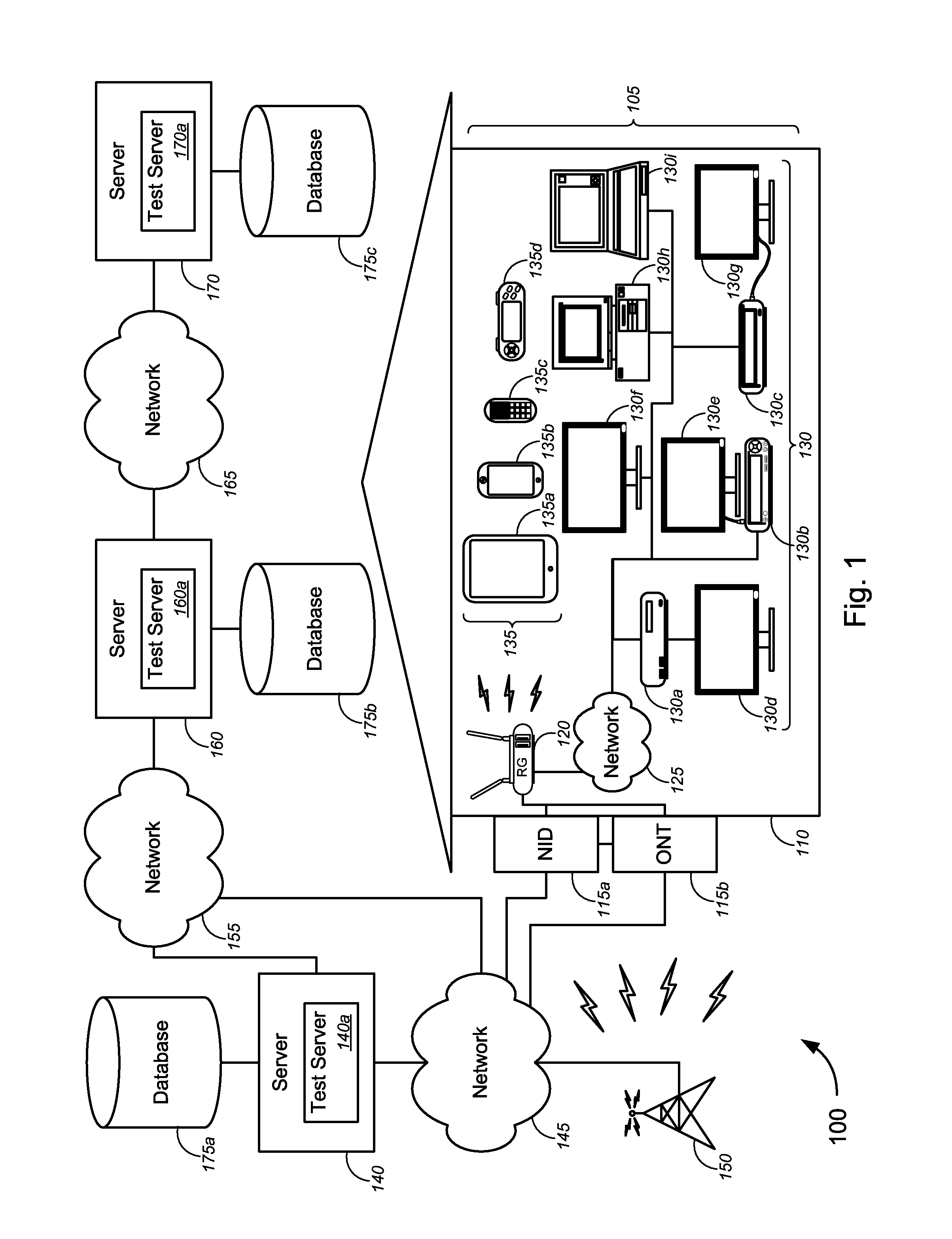
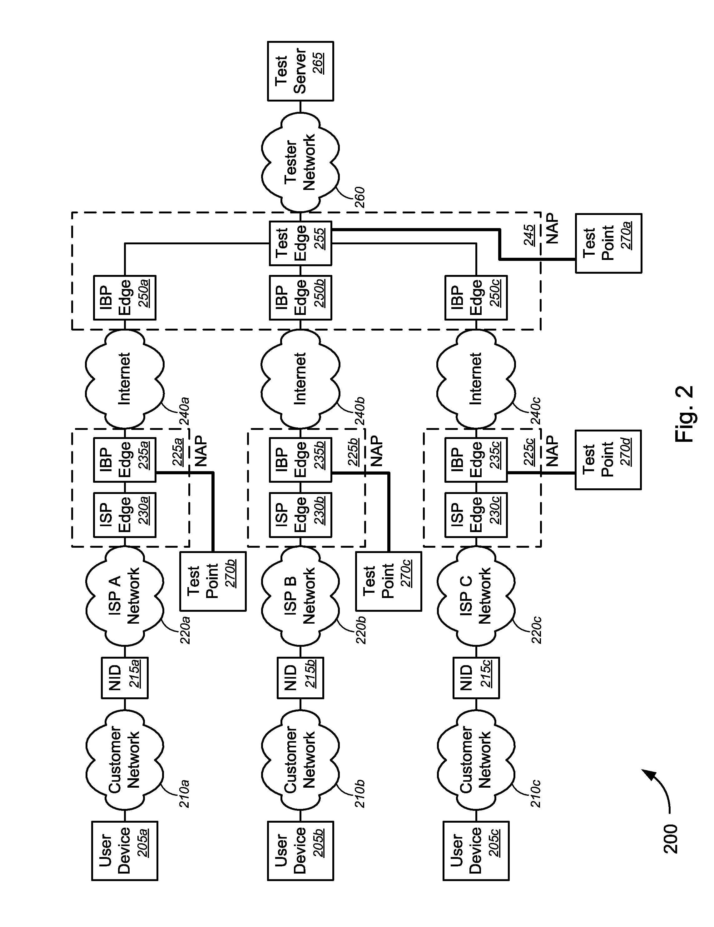
[0012]Various embodiments provide techniques for testing performance of a network connection, and, in some cases, utilizing control groups to test performance of the network connection.

Problems solved by technology

In a cloud environment, or in any computing network, failures or reduced performance along any number of “paths” between a source (e.g., a website server) and a user device can occur due to one or more of a host of events or causes, including, but not limited to, data traffic congestion, faulty hardware or hardware failure, insufficient network connections and / or nodes, electrical surges, natural or manmade disasters, inefficient routing protocols, and / or software glitches, etc.
At present, there are insufficient testing points and servers that accurately monitor segments of interest within computing networks, which might include various networks that are administratively separate from each other (i.e., controlled, operated, and / or maintained by different Internet service providers (“ISPs”)).
In other cases, because of insufficient monitoring of all network connections, even if less congested alternate “paths” exist, it is not possible or practical to easily and effectively identify such alternate “paths” for redirecting or rerouting the data traffic, especially as data congestion factors and effects can change rapidly and unexpectedly.
In sum, any existing networking performance monitoring systems either are inadequate to the task of accurately testing performance (and, in some cases, capacity) of particular segments of interest, are incapable of autonomously or automatically rerouting along higher capacity “paths,” are too costly to ensure adequate monitoring, and / or take too long to gather and analyze the appropriate network performance metrics.

Method used


Image

  • Control Groups for Network Testing
  • Control Groups for Network Testing
  • Control Groups for Network Testing

Examples


Embodiment Construction

[0039]While various aspects and features of certain embodiments have been summarized above, the following detailed description illustrates a few exemplary embodiments in further detail to enable one of skill in the art to practice such embodiments. The described examples are provided for illustrative purposes and are not intended to limit the scope of the invention.

[0040]In the following description, for the purposes of explanation, numerous specific details are set forth in order to provide a thorough understanding of the described embodiments. It will be apparent to one skilled in the art, however, that other embodiments of the present invention may be practiced without some of these specific details. In other instances, certain structures and devices are shown in block diagram form. Several embodiments are described herein, and while various features are ascribed to different embodiments, it should be appreciated that the features described with respect to one embodiment may be i...


PUM


Abstract

Novel tools and techniques are provided for testing performance of network connections. In some cases, a method for testing performance of a network connection might comprise establishing a plurality of test points within one or more segments in the network connection. With a computer, performance of a selected segment of the network connection at one or more first test points may be tested. The selected segment might have a first endpoint and a second endpoint. The performance of one or more sub-segments of the selected segment at one or more second test points may also be tested with the computer. The computer may also determine an isolated performance of a particular one of the sub-segments based on the testing. In some instances, the method might further comprise determining, with the computer, that performance of the one or more sub-segments has affected performance of the network connection.

Description

CROSS-REFERENCES TO RELATED APPLICATIONS[0001]This application claims priority to U.S. Patent Application Ser. No. 61 / 846,439 (the “'439 application”), filed Jul. 15, 2013 by Michael K. Bugenhagen (attorney docket no. 020370-011501US), entitled, “Control Groups for Network Testing.”[0002]This application also claims priority to U.S. Patent Application Ser. No. 61 / 870,395 (the “'395 application”), filed Aug. 27, 2013 by Michael K. Bugenhagen (attorney docket no. 020370-011502US), entitled, “Control Groups for Network Testing.”[0003]The entire disclosure of each of these applications is incorporated herein by reference in its entirety for all purposes.COPYRIGHT STATEMENT[0004]A portion of the disclosure of this patent document contains material that is subject to copyright protection. The copyright owner has no objection to the facsimile reproduction by anyone of the patent document or the patent disclosure as it appears in the Patent and Trademark Office patent file or records, but o...

Claims


Application Information

Patent Timeline
Patent Type & Authority Applications(United States)
IPC IPC(8): H04L12/26G06F11/30
CPCH04L43/0811G06F11/3006H04L43/0835H04L43/087H04L43/0888H04L43/10H04L43/16H04L43/50H04L41/0677H04L67/00
Inventor BUGENHAGEN, MICHAEL K.
Owner CENTURYLINK INTPROP
Why Eureka
Try Eureka