Image capture apparatus and control method therefor

a technology of image capture and control method, which is applied in the field of image capture apparatus, can solve the problems of reducing the accuracy, increasing the amount of computation necessary for high-accuracy estimation, and making the estimation itself difficult, so as to improve optical aberration correction, and the effect of improving the accuracy of hand movement correction

Active Publication Date: 2015-01-22
CANON KK
View PDF9 Cites 25 Cited by
  • Summary
  • Abstract
  • Description
  • Claims
  • Application Information

AI Technical Summary

Benefits of technology

[0009]The present invention has been made in view of the above problems of conventional techniques. The present invention provides an image capture apparatus and a control method therefor, the image capture apparatus being capable of improving the accuracy of hand movement correction, optical aberration correction, and the like by applying geometric deformation processing based on orientation information of an image capture apparatus to an image for which optical shake correction has been performed.

Problems solved by technology

However, a method for detecting and estimating an image distortion using motion vectors at the time of application of the geometric deformation processing lowers the accuracy depending on scenes, increases an amount of computation necessary for high-accuracy estimation, and makes the estimation itself difficult.
For example, in the case of a low-contrast image, such as an image captured indoors, it is more likely that motion vectors fail to be detected and erroneous motion vectors are detected.
Therefore, for example, if a rolling shutter distortion is corrected in accordance with a moving subject, there is a possibility of the occurrence of harmful effects, e.g., a distortion of a portion that is supposed to be still, and a continuous image shake after the correction.
Furthermore, if a rolling shutter distortion in the roll direction is estimated from motion vectors simultaneously with the shake, there will be more estimation variables, leading to an explosive increase in an amount of computation and destabilization of solution estimation.
Furthermore, it is basically not easy to estimate a rolling shutter distortion from motion vectors with high accuracy.
Moreover, the difficulty will further increase if correction parameters for a radial distortion and optical aberration such as transverse chromatic aberration are simultaneously estimated from motion vectors.

Method used


Image

  • Image capture apparatus and control method therefor
  • Image capture apparatus and control method therefor
  • Image capture apparatus and control method therefor

Examples


first embodiment

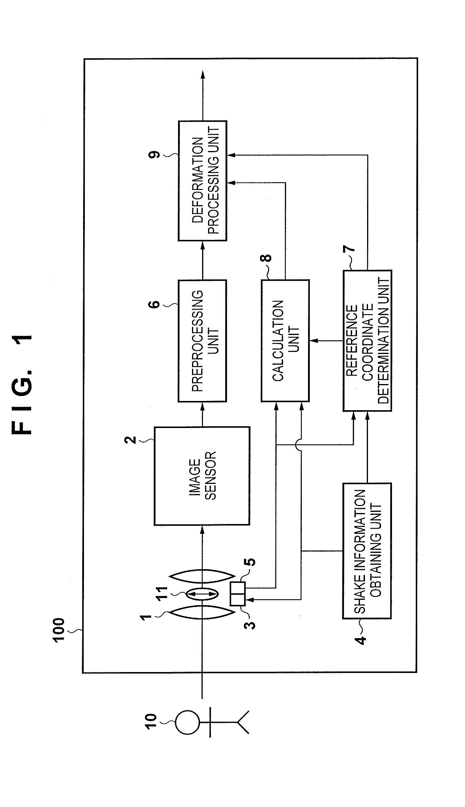
[0025]An exemplary embodiment of the present invention will now be described in detail with reference to the attached drawings. FIG. 1 shows an example of a functional configuration of a digital camera 100, which is one example of an image capture apparatus according to a first embodiment of the present invention, related to anti-shake control. In FIG. 1, a part of a configuration of a general digital camera that is not directly related to the present invention is omitted.

[0026]Optics 1 is an imaging optical system that include a plurality of lenses, such as a focus lens and a shake correction lens 11, and focus incident light from a subject 10 onto an imaging surface of an image sensor 2. The image sensor 2, which is a CCD image sensor or a CMOS image sensor, is composed of a plurality of pixels that are two-dimensionally arrayed. It is assumed that the image sensor 2 according to the present embodiment is a CMOS image sensor as the present embodiment describes an example in which ...

second embodiment

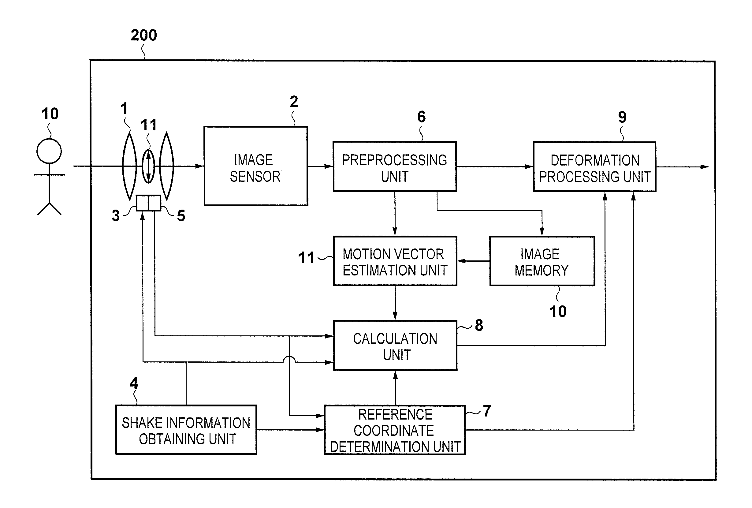
[0095]FIG. 11 shows an example of a functional configuration of a digital camera 200, which is one example of an image capture apparatus according to a second embodiment of the present invention, related to anti-shake control. In FIG. 11, constituents that are similar to those of the digital camera 100 according to the first embodiment are given the same reference numerals thereas, and a description thereof is omitted.

[0096]An image memory 10 temporarily stores a captured image generated by the preprocessing unit 6.

[0097]A motion vector estimation unit 11 detects motion vectors or corresponding points between a captured image temporarily stored in the image memory 10 and a captured image directly input from the preprocessing unit 6.

[0098]The calculation unit 8 according to the present embodiment not only has a function of calculating an amount of geometric deformation using only information from the shake information obtaining unit 4 and the monitoring unit 5 as described in the fir...


PUM


Abstract

An image capture apparatus has an image sensor and an optical anti-shake mechanism that reduces a shake of a captured image by driving an optical correction element in a different direction from an optical axis of an imaging optical system in accordance with a detected shake. Reference coordinates for geometric deformation processing applied to the captured image are determined based on an amount and direction of a movement of the optical correction element. The geometric deformation processing is applied to the captured image using these reference coordinates and an amount of geometric deformation based on the detected shake. Coordinates of the captured image corresponding to an intersection of the optical axis and the image sensor before the optical correction element is moved through the driving are determined as the reference coordinates.

Description

BACKGROUND OF THE INVENTION[0001]1. Field of the Invention[0002]The present invention relates to an image capture apparatus and a control method therefor, and in particular to an image capture apparatus with an optical anti-shake mechanism and a control method therefor.[0003]2. Description of the Related Art[0004]Conventionally, a so-called image stabilization function is known that corrects (alleviates) blurring of a captured image (image shake) caused by a movement of an image capture apparatus, and representative methods for realizing the image stabilization function include optical image stabilization and electronic image stabilization (Japanese Patent Laid-Open No. 2011-145604). The optical image stabilization is a method for reducing a movement of an image of a subject by moving optical elements such as a shift lens and an image sensor based on a detected amount of shake of an image capture apparatus. On the other hand, the electronic image stabilization is a method for reduci...

Claims


Application Information

Patent Timeline
Patent Type & Authority Applications(United States)
IPC IPC(8): H04N5/232
CPCH04N5/23287H04N23/6811H04N23/687
Inventor TSUBAKI, HIDETOSHI
Owner CANON KK
Why Eureka
Try Eureka