Touchscreen sensor

Active Publication Date: 2015-01-22
NITTO DENKO CORP
View PDF12 Cites 6 Cited by
  • Summary
  • Abstract
  • Description
  • Claims
  • Application Information

AI Technical Summary

Benefits of technology

The patent text describes a technology for making a touchscreen sensor that can reduce interference fringes. This is achieved by using special layers with specific refractive indexes and thicknesses between the transparent base material and the transparent electrodes. The result is a more reliable and high-quality touchscreen sensor.

Problems solved by technology

However, with a configuration as described above in which transparent electrode patterns are formed at both sides of the transparent base material, when a touchscreen sensor is fabricated by directly laminating an adhesive layer on each of the transparent electrode patterns, there is a problem that interference fringes may be produced when light from outside is incident thereon.

Method used


Image

  • Touchscreen sensor
  • Touchscreen sensor

Examples


example 1

[0045]A hardcoat layer containing spherical particles of 3 μm in diameter was formed sequentially on both sides of a transparent base material made of a polycycloolefin film (manufactured by Nippon Zeon Corporation, product name ZEONOR) having a thickness of 100 μm. Thereafter, on each of the hardcoat layers, an inorganic-organic composite material (manufactured by JSR Corporation, product name OPSTAR KZ6661) in which inorganic particles are scattered in an organic component of a photosensitive monomer was applied and light cured to form the first and third index-matching layers each having a refractive index of 1.65 and a thickness of 100 nm.

[0046]Then, the transparent base material was placed in a sputtering device in which a sintered target containing indium oxide of 97% by weight and tin oxide of 3% by weight was installed, and an indium tin oxide layer having a thickness of 27 nm was formed at one side of the transparent base material by sputtering. Thereafter, a process simila...

example 2

[0050]A touchscreen sensor was fabricated with a method similar to the method of Example 1, except that a thickness of each of the first, second, third and fourth index-matching layers was 85 nm, respectively.

example 3

[0051]A touchscreen sensor was fabricated with a method similar to the method of Example 1, except that a thickness of each of the first, second, third and fourth index-matching layers was 120 nm, respectively.


PUM

PropertyMeasurementUnit
Thicknessaaaaaaaaaa
Thicknessaaaaaaaaaa
Thicknessaaaaaaaaaa

Abstract

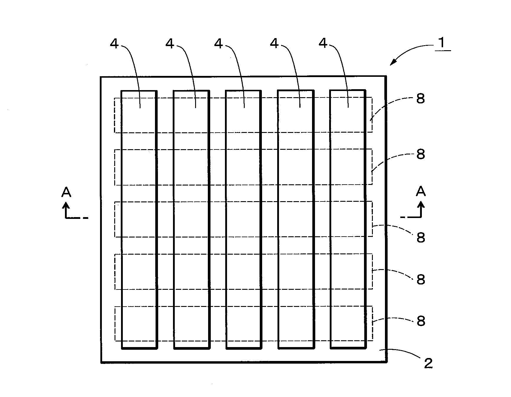
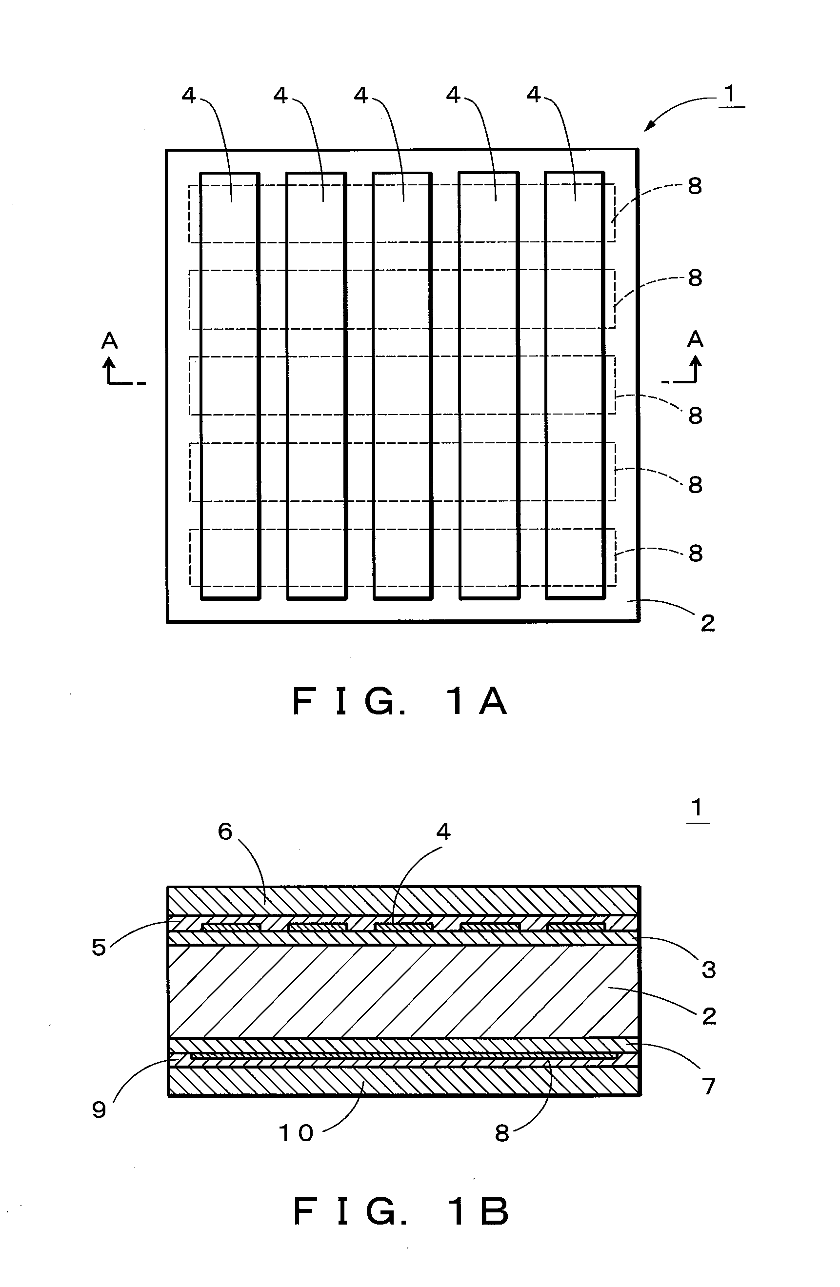
A touchscreen sensor includes a transparent base material, a first index-matching layer, a first transparent electrode pattern, a second index-matching layer and a first adhesive layer disposed in this order at one side of the transparent base material, and a third index-matching layer, a second transparent electrode pattern, a fourth index-matching layer and a second adhesive layer disposed in this order at another side of the transparent base material. Each of the first, second, third and fourth index-matching layers has a refractive index of 1.6 to 1.8 and a thickness of 50 nm to 150 nm.

Description

CROSS REFERENCE TO RELATED APPLICATIONS[0001]This is a continuation application of International Patent Application No. PCT / JP2014 / 060369 filed Apr. 10, 2014, which claims the benefit of Japanese Patent Application No. 2013-111287, filed May 27, 2013, the full contents of all of which are hereby incorporated by reference in their entirety.BACKGROUND[0002]1. Technical Field[0003]The present disclosure relates to a touchscreen sensor applicable to an input display device that is capable of inputting information by a touch with a finger, a stylus pen and the like.[0004]2. Background Art[0005]In the related art, laminated film having a transparent conductor layer at both sides of a transparent base material is known (Japanese Laid-Open Patent Publication No. 2012-066477). Such a laminated film enables accurate patterning of each of the transparent conductor layers and thus has a high relative positional accuracy of transparent electrode patterns.[0006]However, with a configuration as de...

Claims


Application Information

Patent Timeline
IPC IPC(8): G06F3/041G02B1/11
CPCG02B1/11G06F3/041G06F3/044G06F3/0412G06F2203/04103G06F3/0445G06F3/0446
Inventor TAKAO, HIROYUKIUMEMOTO, TORU
Owner NITTO DENKO CORP
Why Eureka
Try Eureka