Fuel cell and cathode material
a fuel cell and cathode material technology, applied in the direction of cell components, electrochemical generators, electrolytes, etc., can solve the problem of increasing initial output and achieve the effect of increasing initial outpu
- Summary
- Abstract
- Description
- Claims
- Application Information
AI Technical Summary
Benefits of technology
Problems solved by technology
Method used
Image
Examples
first embodiment
1. First Embodiment
Configuration of Fuel Cell 10
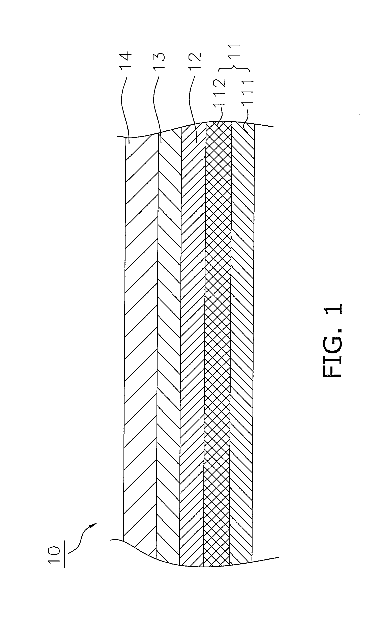
[0028]The configuration of a fuel cell (abbreviated below to “cell”) 10 will be described making reference to the figures. FIG. 1 is a cross sectional view of the configuration of the cell 10.
[0029]The cell 10 is a thin tabular body configured using a ceramic material. The thickness of the cell 10 is for example 300 micrometers to 3 mm, and the diameter of the cell 10 is 5 mm to 50 mm. A plurality of cells 10 is connected in series by an interconnector to form a fuel cell.
[0030]The cell 10 includes an anode 11, a solid electrolyte layer 12, a barrier layer 13 and a cathode 14.
[0031]The anode 11 has the function of an anode of the cell 10. The anode 11 as illustrated in FIG. 1 is configured from an anode current collector 111 and an anode active layer 112.
[0032]The anode current collector 111 may be configured as a porous tabular fired body including a transition metal and an oxygen ion conductive substance. The anode current collector ...
second embodiment
2. Second Embodiment
Configuration of Fuel Cell 20
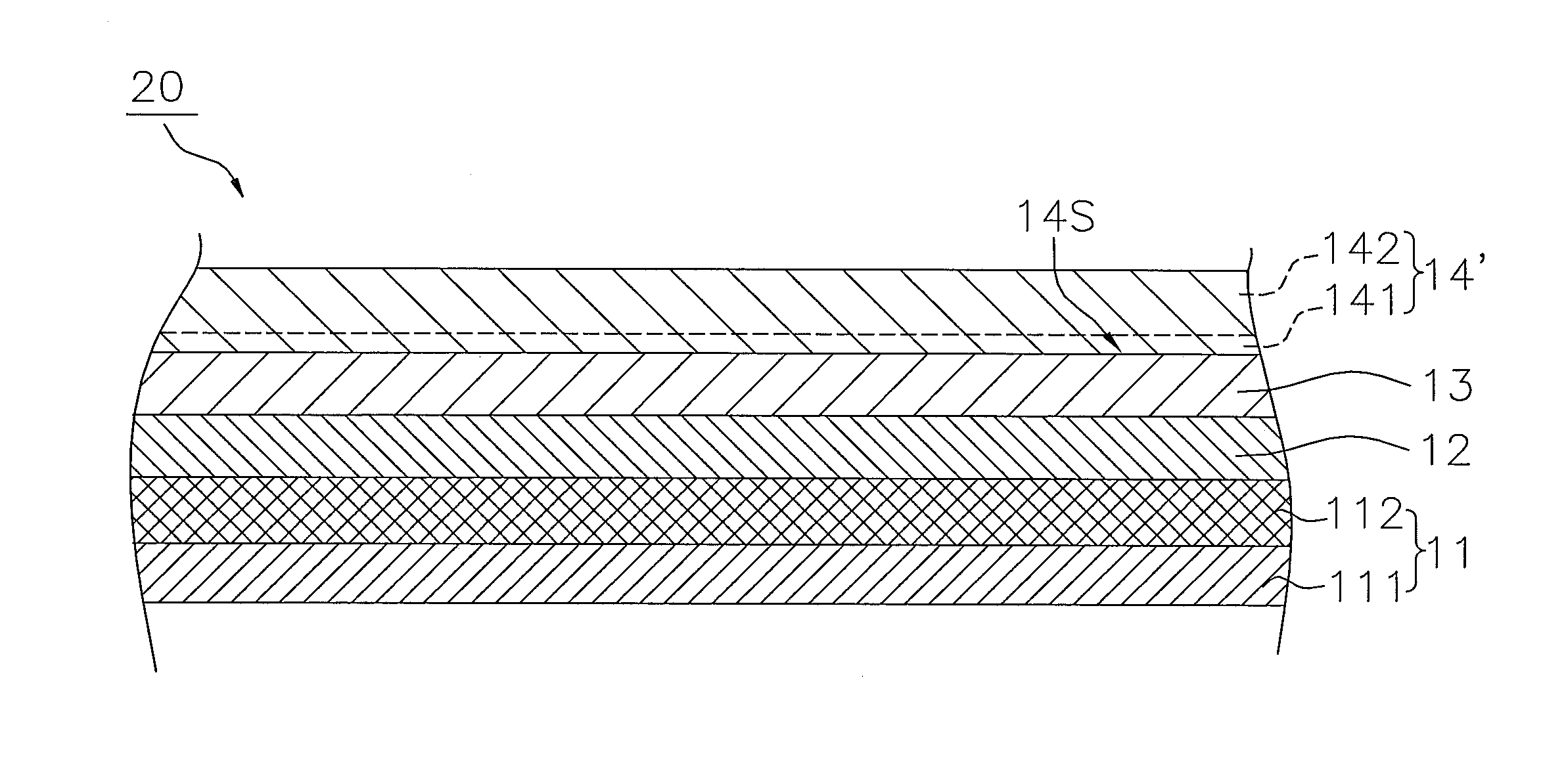
[0065]The configuration of a fuel cell 20 according to a second embodiment will be described making reference to the figures. FIG. 4 is a cross sectional view of the configuration of the cell 20. The point of difference between the cell 10 according to the first embodiment and the cell 20 according to the second embodiment resides in the feature that the occupied area ratio of the sub phase is only managed in relation to the region near the solid electrolyte layer 12 of a cathode 14′. The following description will focus mainly on the point of difference.
[0066]As illustrated in FIG. 4, the cathode 14′ includes a first region 141 and a second region 142.
[0067]The first region is a region within 3 micrometers from the surface 14S near to the solid electrolyte layer 12. That is to say, the thickness of the first region 141 is 3 micrometers. The first region 141 is an example of the “solid electrolyte layer-side region”. The cell 20 accor...
examples
[0095]Although the examples of the fuel cell according to the present invention will be described below, the present invention is not thereby limited to the following examples.
Preparation of Samples No. 1 to No. 20
[0096]As described below, Samples No. 1 to No. 20 of an anode support cell are prepared in which the anode current collection layer is configured as a support base plate.
[0097]Firstly, an anode current collection layer (NiO:8YSZ=50:50 (Ni volume % conversion)) having a thickness of 500 micrometers is formed using a die press molding method. In top of that layer, an anode active layer (NiO:8YSZ=45:55 (Ni volume % conversion)) having a thickness of 20 micrometers is formed using a printing method.
[0098]Then, an 8YSZ electrolyte having a thickness of 5 micrometers and a GDC barrier film having a thickness of 5 micrometers are formed in series on the anode active layer to thereby form a laminated body.
[0099]The laminated body is then co-sintered for two hours at 1400 degrees C...
PUM
| Property | Measurement | Unit |
|---|---|---|
| equivalent circle diameter | aaaaa | aaaaa |
| equivalent circle diameter | aaaaa | aaaaa |
| diameter | aaaaa | aaaaa |
Abstract
Description
Claims
Application Information
 - R&D
- Intellectual Property
- Life Sciences
- Materials
- Tech Scout
- Unparalleled Data Quality
- Higher Quality Content
- 60% Fewer Hallucinations
Browse by: Latest US Patents, China's latest patents, Technical Efficacy Thesaurus, Application Domain, Technology Topic, Popular Technical Reports.
© 2025 PatSnap. All rights reserved.Legal|Privacy policy|Modern Slavery Act Transparency Statement|Sitemap|About US| Contact US: help@patsnap.com


