Plasma etcher chuck band

a technology of chuck band and plasma, which is applied in the direction of electrical discharge tubes, semiconductor/solid-state device testing/measurement, electrical equipment, etc., can solve the problems of inconvenient maintenance of equipment, and the possibility of degradation of polymer materials

Inactive Publication Date: 2015-01-22
TEXAS INSTR INC
View PDF12 Cites 9 Cited by
  • Summary
  • Abstract
  • Description
  • Claims
  • Application Information

AI Technical Summary

Problems solved by technology

The polymer material may be susceptible to degradation from the etch environment, undesirably adding to equipment maintenance costs.

Method used


Image

  • Plasma etcher chuck band
  • Plasma etcher chuck band
  • Plasma etcher chuck band

Examples


Embodiment Construction

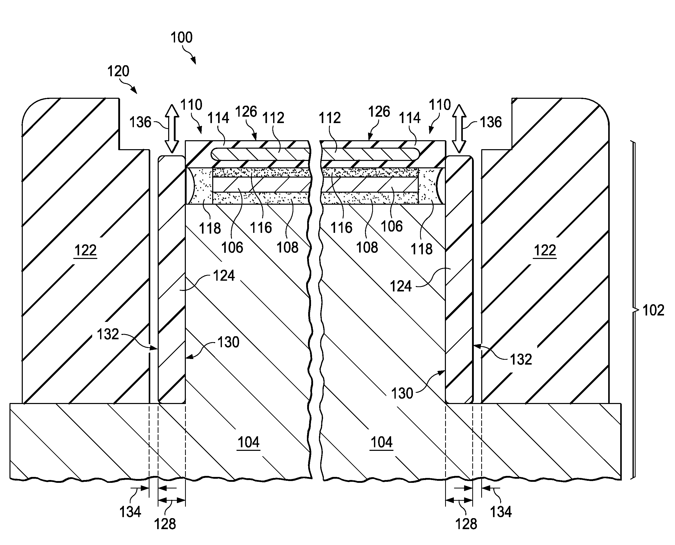
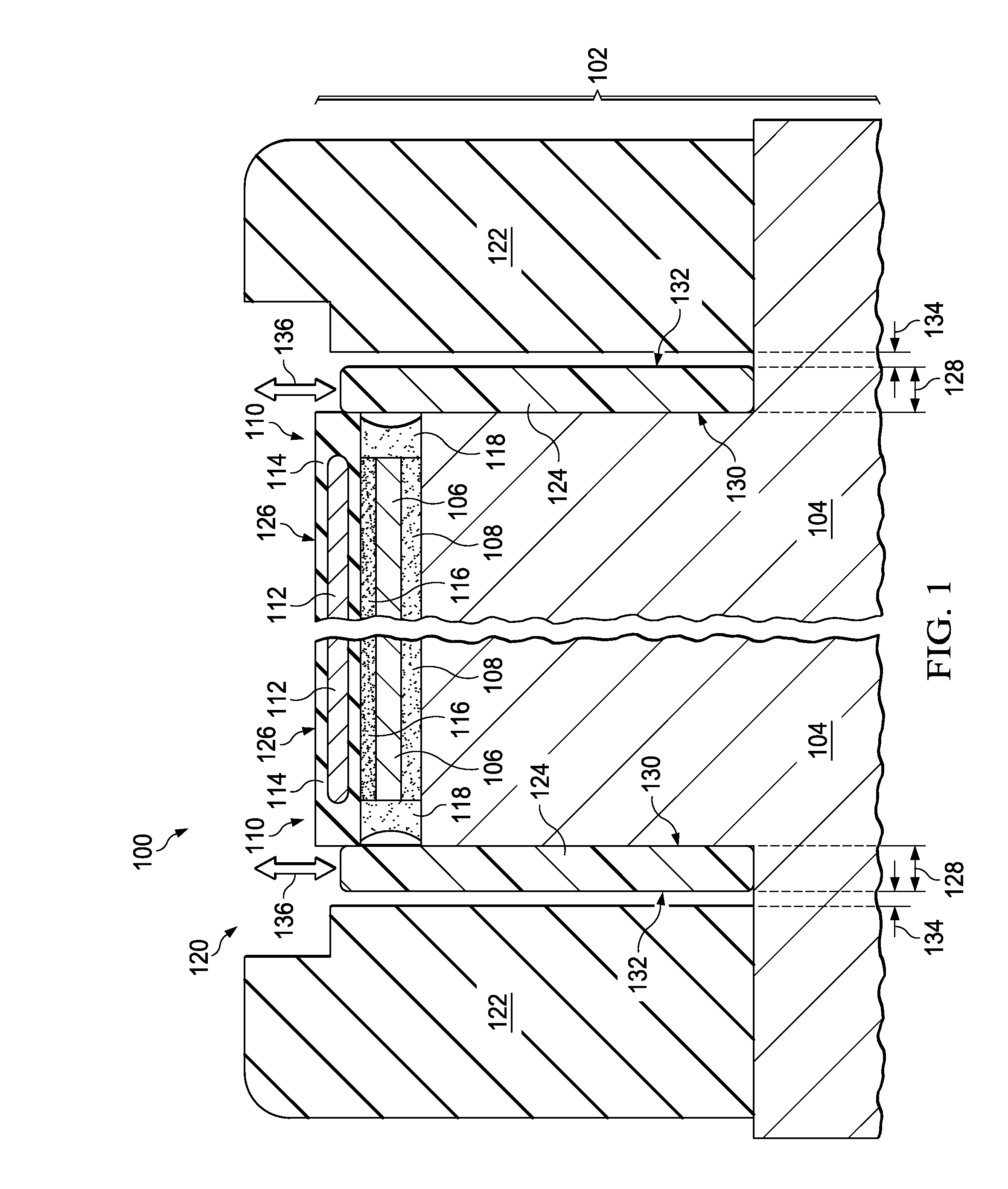
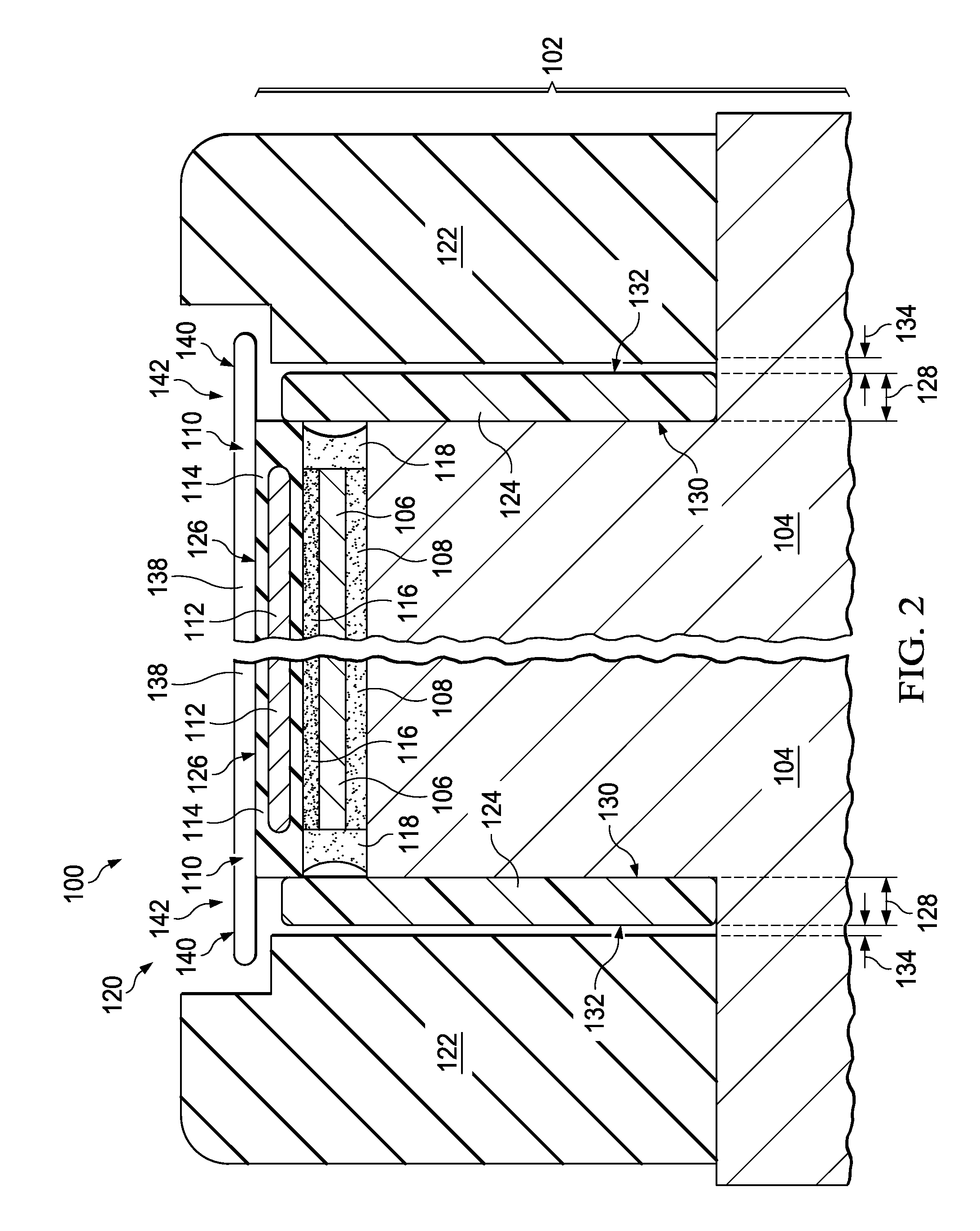
[0011]The present invention is described with reference to the attached figures. The figures are not drawn to scale and they are provided merely to illustrate the invention. Several aspects of the invention are described below with reference to example applications for illustration. It should be understood that numerous specific details, relationships, and methods are set forth to provide an understanding of the invention. One skilled in the relevant art, however, will readily recognize that the invention can be practiced without one or more of the specific details or with other methods. In other instances, well-known structures or operations are not shown in detail to avoid obscuring the invention. The present invention is not limited by the illustrated ordering of acts or events, as some acts may occur in different orders and / or concurrently with other acts or events. Furthermore, not all illustrated acts or events are required to implement a methodology in accordance with the pre...


PUM

PropertyMeasurementUnit
thicknessaaaaaaaaaa
temperatureaaaaaaaaaa
perimeteraaaaaaaaaa

Abstract

A plasma etch tool includes a wafer chuck with a chuck base and at least one functional component layer attached to the chuck base. A perimeter of the functional component layer has a polymer material permanently attached to it that extends to within 2 millimeters of a top surface of the chuck. The top surface of the wafer chuck contacts a bottom surface of a semiconductor wafer during an etch process for forming an integrated circuit. The polymer material is protected from an etch ambient by a plasma etcher chuck band installed around the perimeter of the functional component layer, extending over a portion of the chuck base. An integrated circuit may be formed by installing the plasma etcher chuck band on the chuck of the plasma etch tool, and subsequently performing an etch process in the plasma etch tool on a semiconductor wafer containing the partially formed integrated circuit.

Description

FIELD OF THE INVENTION[0001]This invention relates to the field of process equipment for integrated circuits. More particularly, this invention relates to plasma equipment for integrated circuits.BACKGROUND OF THE INVENTION[0002]A plasma etch tool for fabricating integrated circuits may include a chuck for supporting the wafer which has one or more functional component layers, such as a wafer heater and / or an electrostatic platen attached to the chuck base. The chuck may include a partially exposed polymer material used, for example, to seal edges of the functional component layers or to attach the functional component layers to the chuck base. The polymer material may be susceptible to degradation from the etch environment, undesirably adding to equipment maintenance costs.SUMMARY OF THE INVENTION[0003]The following presents a simplified summary in order to provide a basic understanding of one or more aspects of the invention. This summary is not an extensive overview of the invent...

Claims


Application Information

Patent Timeline
Patent Type & Authority Applications(United States)
IPC IPC(8): H01L21/687H01L21/3065H01L21/66H01L21/67
CPCH01L22/12H01L21/687H01L21/67069H01L21/3065H01L21/68735H01L21/68757H01L21/68785H01J37/32477H01J37/32715
Inventor SHRINER, JOHN, CHRISTOPHER
Owner TEXAS INSTR INC
Why Eureka
Try Eureka