High-voltage coil fixing device of plasma etcher

A technology of high-voltage coils and fixing devices, which is applied to circuits, discharge tubes, electrical components, etc., can solve problems such as unreliable fixing of high-voltage coils, achieve stable magnetic field strength, prolong service life, and improve reliability

Inactive Publication Date: 2010-08-11
EGING PHOTOVOLTAIC TECHNOLOGY CO LTD
View PDF5 Cites 0 Cited by
  • Summary
  • Abstract
  • Description
  • Claims
  • Application Information

AI Technical Summary

Problems solved by technology

[0004] In order to overcome the shortcomings of existing plasma etching machines due to unreliable high-volt

Method used


Image

  • High-voltage coil fixing device of plasma etcher
  • High-voltage coil fixing device of plasma etcher
  • High-voltage coil fixing device of plasma etcher

Examples


Embodiment Construction

[0017] The specific mode of the present invention is described in detail below in conjunction with accompanying drawing:

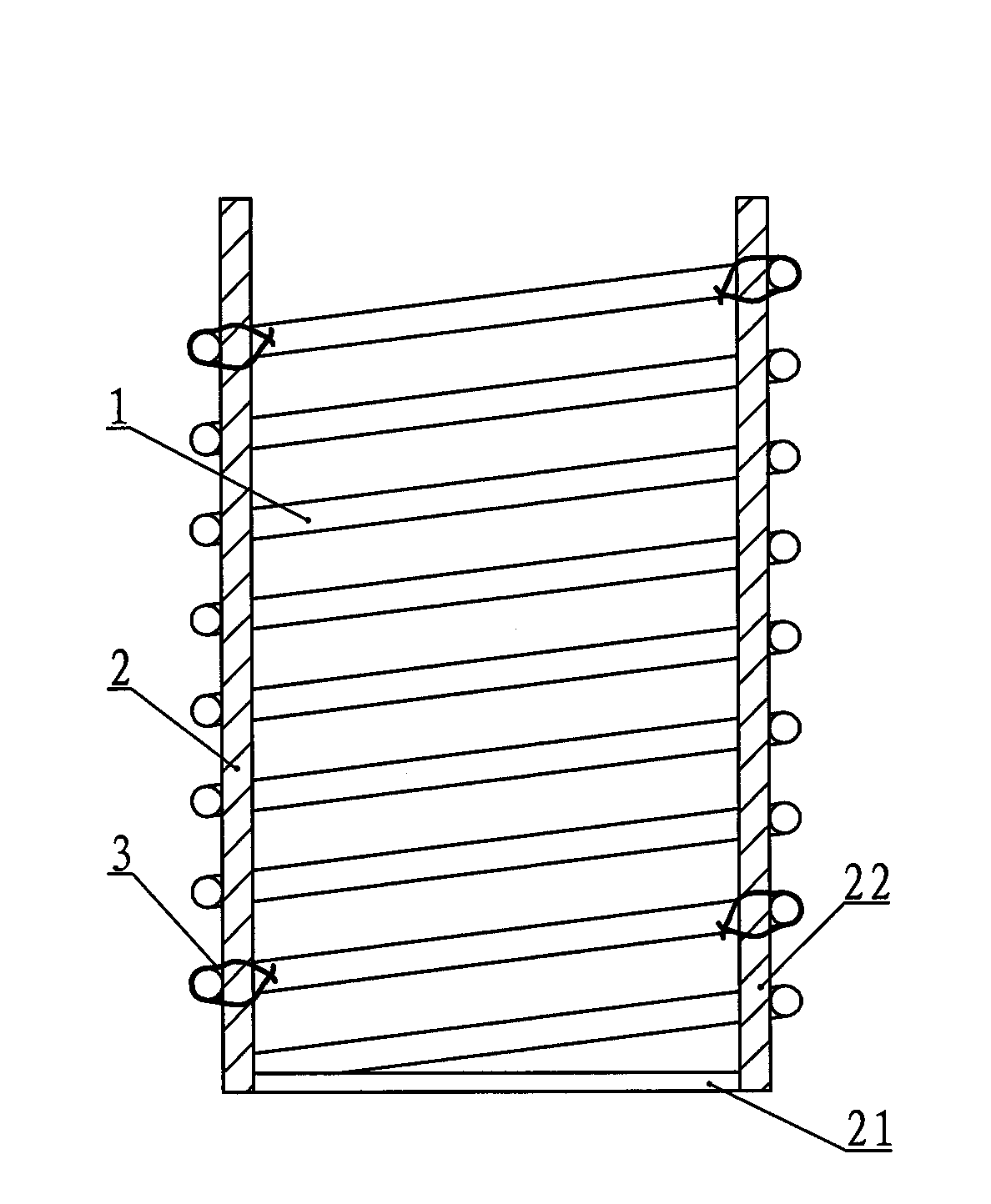
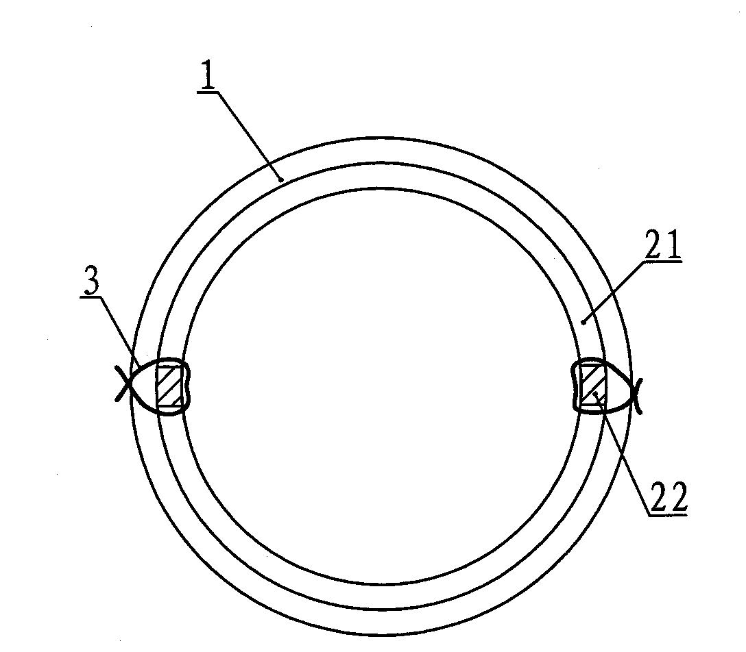
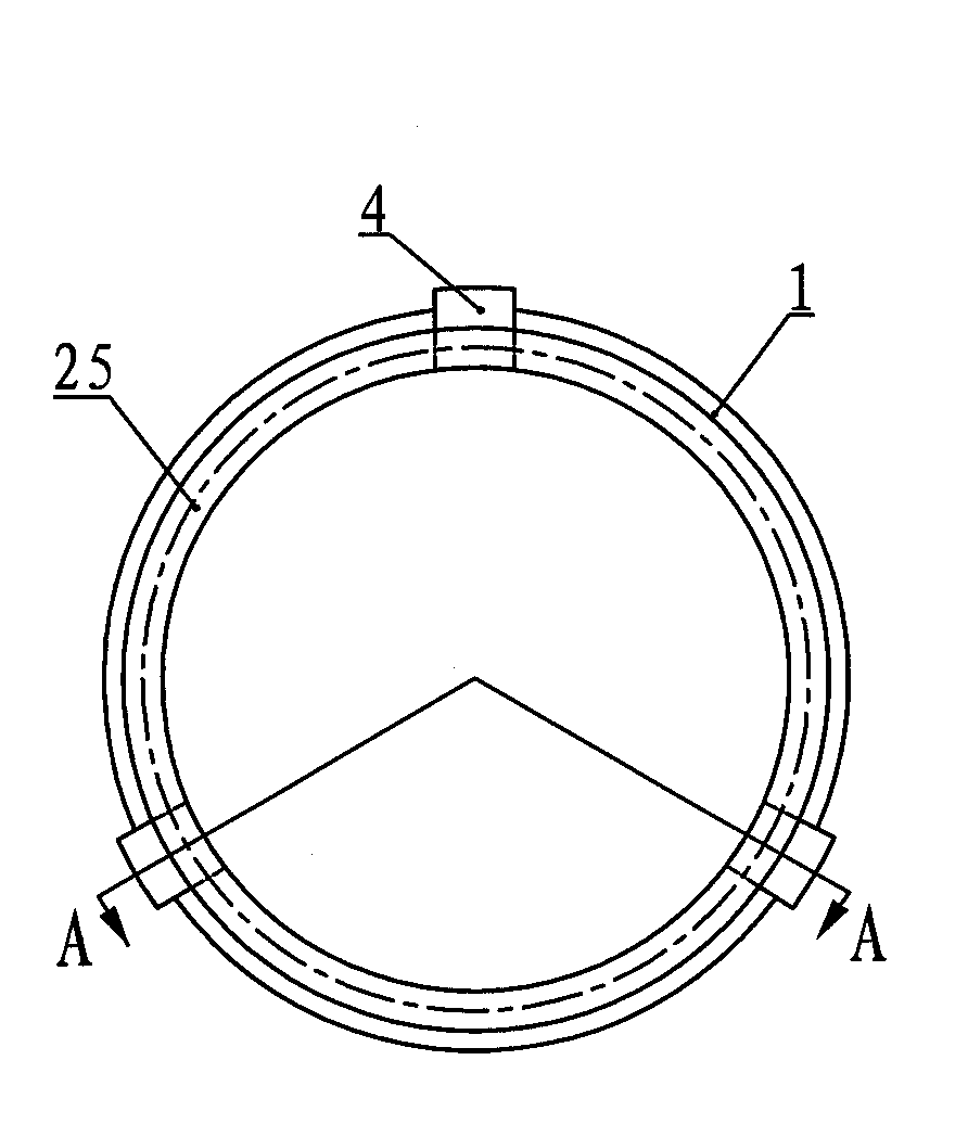
[0018] The high-voltage coil fixing device of the plasma etching machine, such as Figure 3 ~ Figure 5 As shown, it includes a high-voltage coil 1 and a bobbin 2, and the bobbin 2 includes a bottom connection ring 23, a slotted column 24 and a top connection ring 25, and the bottom connection ring 23 and the top connection ring 25 are evenly spaced There are three slotted columns 24, and each slotted column 24 is equidistantly provided with wire slots 26, and the winding inner circle of the high-voltage coil 1 is pressed into the wire slots 26 on the slotted columns 24. The outer side of the slotted column 24 is provided with a strip-shaped pressure plate 4, on which the strip-shaped pressure plate 4 is provided with a crimping groove 41 corresponding to the high-voltage coil 1, and the strip-shaped pressure plate 4 and the slotted column 24 are fixedly co...


PUM


Abstract

The invention relates to a high-voltage coil fixing device of a plasma etcher. A coil skeleton of the device comprises a bottom end connecting ring, upright posts with a groove and a top end connecting ring, wherein more than three upright posts with a groove are uniformly arranged between the bottom end connecting ring and the top end connecting ring; line containing grooves are arranged on each upright post with a groove at equal intervals; the outer side of the upright posts with a groove is provided with a strip pressing plate, and a line pressing groove corresponding to a high-voltage coil is arranged on the strip pressing plate; and the strip pressing plate and the upright posts with a groove are fixedly connected into a whole by bolts. Because the coil skeleton with better rigidity and the strip pressing plate are used to fix the high-voltage coil, the high-voltage coil cannot deform and be separated from the coil skeleton so as to radically eliminate accidents of striking a quartz reaction tube because a winding of the high-voltage coil separates from the coil skeleton, thereby guaranteeing the normal service life of the quartz reaction tube, improving the use reliability of the plasma etcher and saving the production cost.

Description

Technical field: [0001] The invention relates to plasma etching equipment, in particular to a high-voltage coil fixing device for a plasma etching machine. Background technique: [0002] Solar energy is a kind of radiant energy, which must be transformed into electrical energy by means of an energy converter. This energy converter that converts solar energy into electrical energy is commonly known as a solar cell. The P-N junction is the core part of a crystalline silicon solar cell. Without a P-N junction, photocurrent cannot be generated, and a solar cell cannot be formed. Diffusion is a way for silicon wafers to make P-N junctions. However, during the diffusion process, a diffusion layer is also formed on the peripheral surface of silicon wafers. The diffusion layer on the peripheral surface of the silicon wafer will form a short circuit ring between the upper and lower electrodes of the battery and must be removed. Any small local short circuit on the periphery will r...

Claims


Application Information

Patent Timeline
IPC IPC(8): H01J37/02
Inventor 朱国平
Owner EGING PHOTOVOLTAIC TECHNOLOGY CO LTD
Why Eureka
Try Eureka