
Method And Device For Determining The Speed And/Or Position Of A Vehicle

a technology for determining the speed and/or position of a vehicle, applied in the direction of vehicle position/course/altitude control, process and machine control, instruments, etc., can solve the problems of prone to major errors, difficult to determine in particular the position value, and inconvenient to determine the position value, so as to achieve the effect of estimating the position and/or speed of the driver's vehicle more simply and more reliably

Active Publication Date: 2015-01-22
CONTINENTAL AUTOMOTIVE GMBH
View PDF3 Cites 19 Cited by
  • Summary
  • Abstract
  • Description
  • Claims
  • Application Information

AI Technical Summary

Benefits of technology

The present invention provides a method to estimate the position and speed of a moving vehicle more accurately and reliably. This is achieved by determining the absolute position of an object at rest relative to an object in motion using a surround sensor and placing it in an absolute coordinate system. The method is less prone to errors and reduces the impact of errors arising from, for example, satellite navigation. Additionally, the method combines data from different sensor technologies to improve accuracy and reliability. The weighting factor used in the method takes into account the accuracy and dimensions of an object to give greater weight and improve the position estimation.

Problems solved by technology

Owing to the fact that the position and / or speed of the vehicle is determined relative to the objects located in the vehicle surroundings and detected by sensors, the values obtained are known only relative to the vehicles and also contain errors.
In addition, determining the values takes a relatively long time because it is necessary to track the objects and then analyze this tracking.
In addition, satellite data for determining the position of the moving objects is often not available reliably, especially in built-up environments containing streets of high-rise buildings, with the result that determining in particular the position value is difficult and prone to major errors.

Method used


Image

  • Method And Device For Determining The Speed And/Or Position Of A Vehicle
  • Method And Device For Determining The Speed And/Or Position Of A Vehicle
  • Method And Device For Determining The Speed And/Or Position Of A Vehicle

Examples


Embodiment Construction

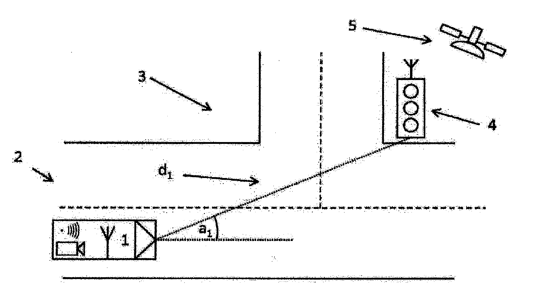
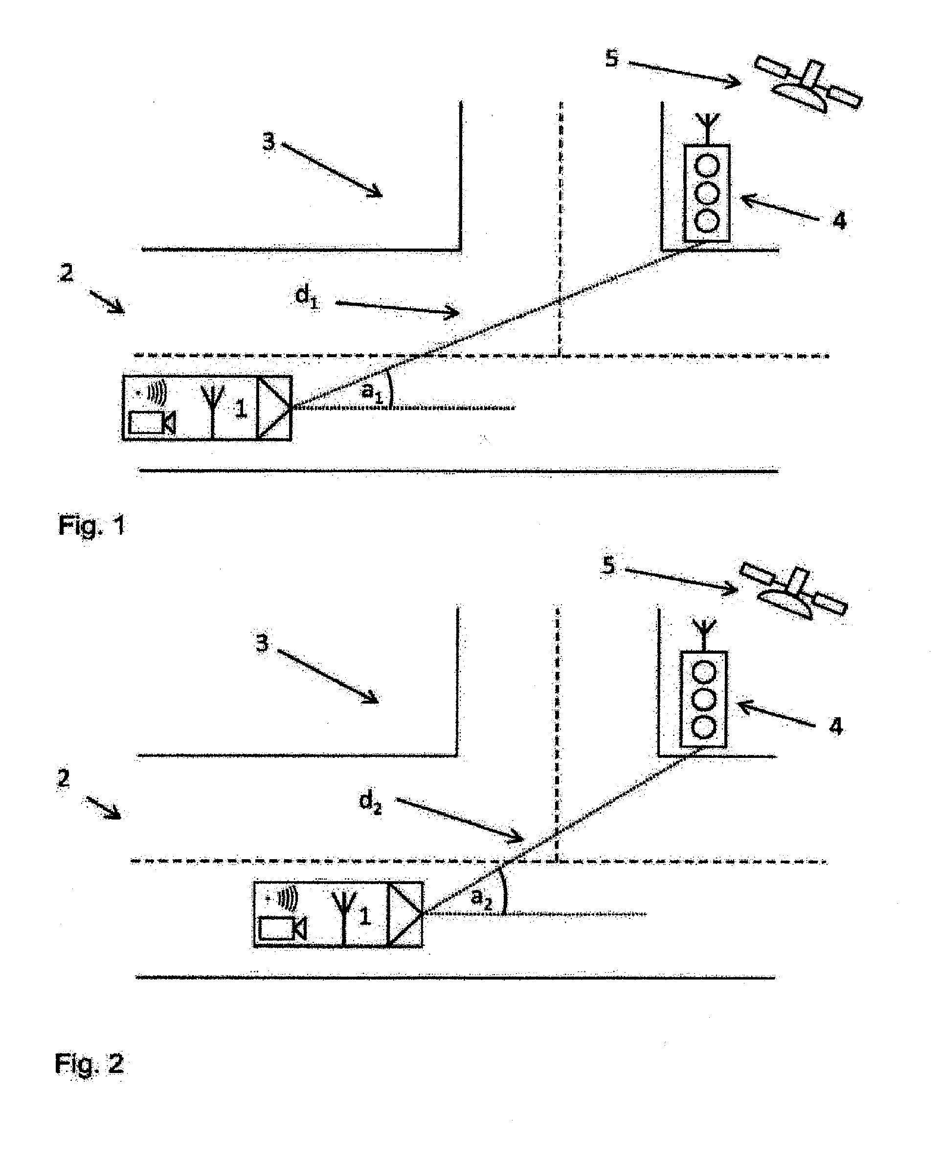
[0034]FIG. 1 shows a vehicle 1 located on a roadway 2. The vehicle 1 is moving towards a crossroads 3 at which a motionless object 4 is located. The motionless object 4 is a set of traffic lights arranged in a stationary manner on the opposite side of the crossroads 3 from the vehicle.

[0035]Both the vehicle 1 and the set of traffic lights 4 participate in the vehicle-to-environment communication. As part of the standardized vehicle-to-environment communication, the set of traffic lights 4 transmits messages. These messages contain the speed, position and dimensions of the set of traffic lights 4. Since the set of traffic lights 4 is a stationary object, the speed is equal to zero. The vehicle 1 receives these messages by its antenna. In the processing unit of the vehicle 1, this message is analyzed and it is established that a motionless object is in the surroundings.

[0036]Then the set of traffic lights 4 is detected by surround sensors of the vehicle 1. The surround sensors are a r...


PUM


Abstract

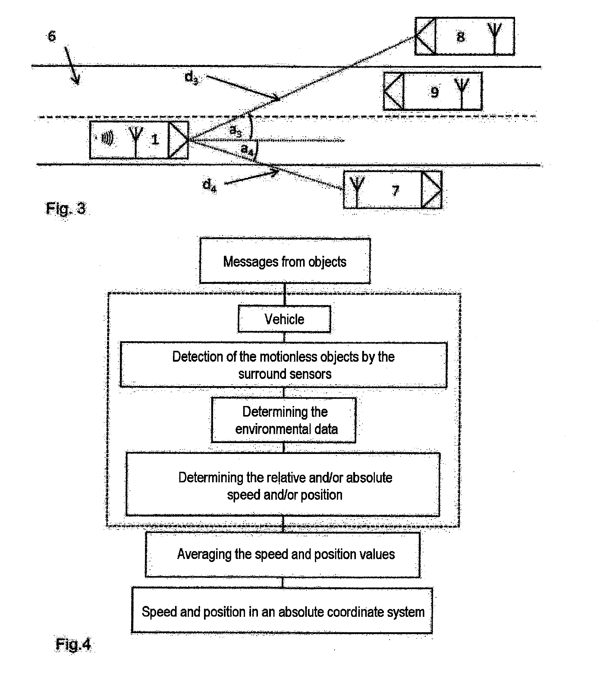
A method for determining the speed of a vehicle equipped with at least one surround sensor that determines environment data of the vehicle relative to at least one motionless object includes: receiving, by the vehicle, through wireless vehicle-to-environment communication with the at least one motionless object, a transmitted piece of information about the motionlessness of the motionless object; determining the relative motion of the vehicle with respect to the motionless object from the environment data of the vehicle relative to the motionless object; and determining the speed of the vehicle and / or the relative position of the vehicle with respect to the motionless object from the determined relative motion.

Description

CROSS-REFERENCE TO RELATED APPLICATIONS[0001]This is a U.S. national stage of application No. PCT / EP2013 / 053760, filed on 26 Feb. 2013, which claims priority to the German Application No. DE 102012203037.9 filed 28 Feb. 2012, the content of both incorporated herein by reference.BACKGROUND OF THE INVENTION[0002]1. Field of the Invention[0003]The invention relates to a method for determining the speed of a vehicle equipped with at least one surround sensor that determines environment data of the vehicle relative to at least one motionless object, and to a device for carrying out this method.[0004]Surround sensors shall be understood to mean detection devices that use measurements to detect and map a vehicle's surroundings. The environment data output by the surround sensor describes objects detected by the measurements relative to the driver's vehicle. Thus, the environment data contains in particular a piece of information about a relative distance between the vehicle and the detecte...

Claims


Application Information

Patent Timeline
IPC IPC(8): B60W40/105
CPCB60W40/105B60W2420/54B60W2420/42B60W2420/52B60W2550/40G06F17/00B60W2556/45B60W2420/408B60W2420/403
Inventor HOHM, ANDREEKOMAR, MATTHIASSTAHLIN, ULRICH
Owner CONTINENTAL AUTOMOTIVE GMBH
Learn More