Cooling system

Inactive Publication Date: 2015-01-29
TOYOTA JIDOSHA KK
View PDF0 Cites 14 Cited by
  • Summary
  • Abstract
  • Description
  • Claims
  • Application Information

AI Technical Summary

Benefits of technology

[0016]With the above-described cooling system, it is possible to efficiently cool the he

Problems solved by technology

Therefore, there is a problem that a fuel consumpti

Method used


Image

  • Cooling system
  • Cooling system
  • Cooling system

Examples


Embodiment Construction

[0029]Hereinafter, an embodiment of the invention will be described with reference to the accompanying drawings. Note that like reference numerals denote the same or corresponding portions in the drawings and the description thereof is not repeated.

Configuration of Cooling System 1

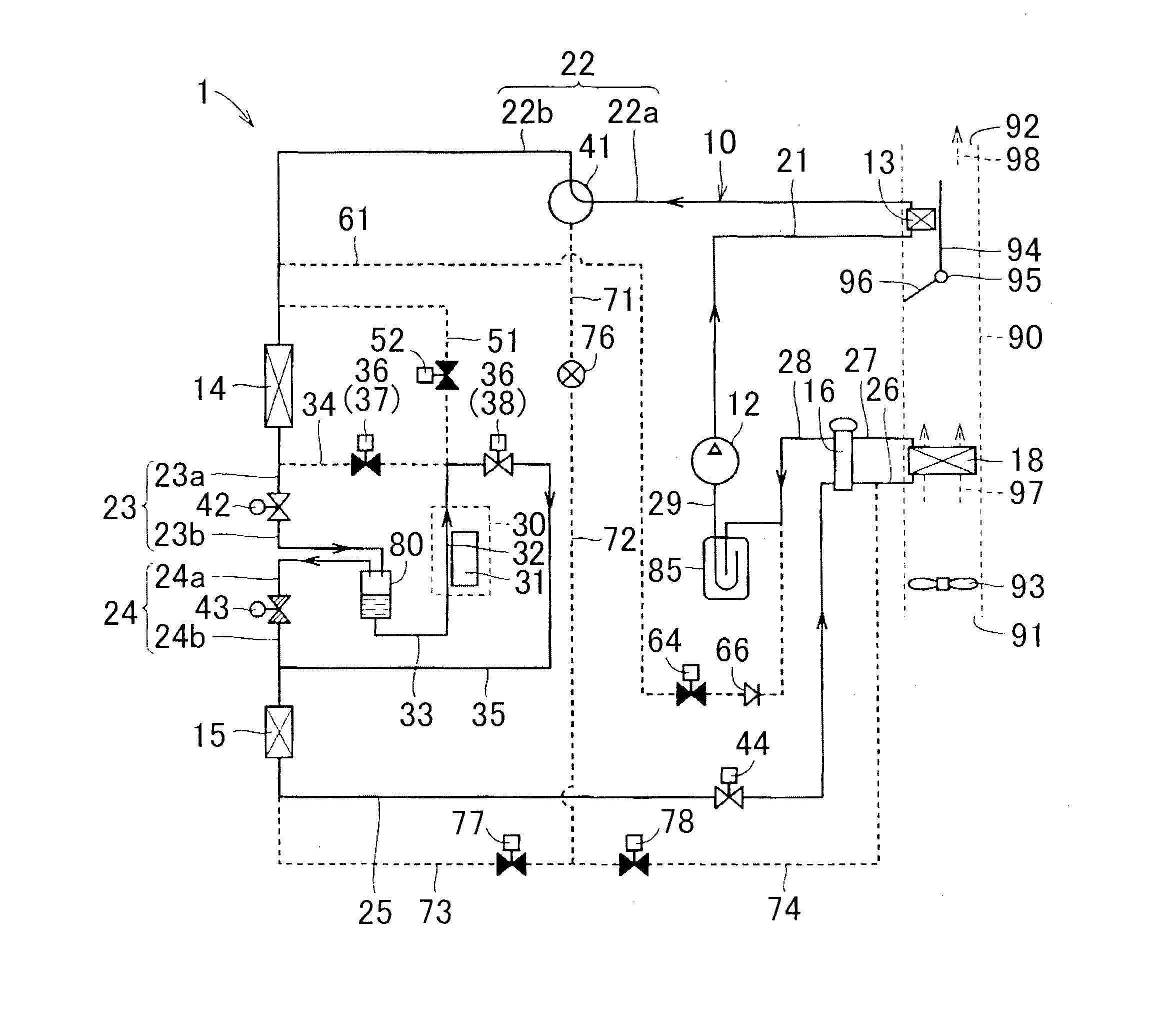
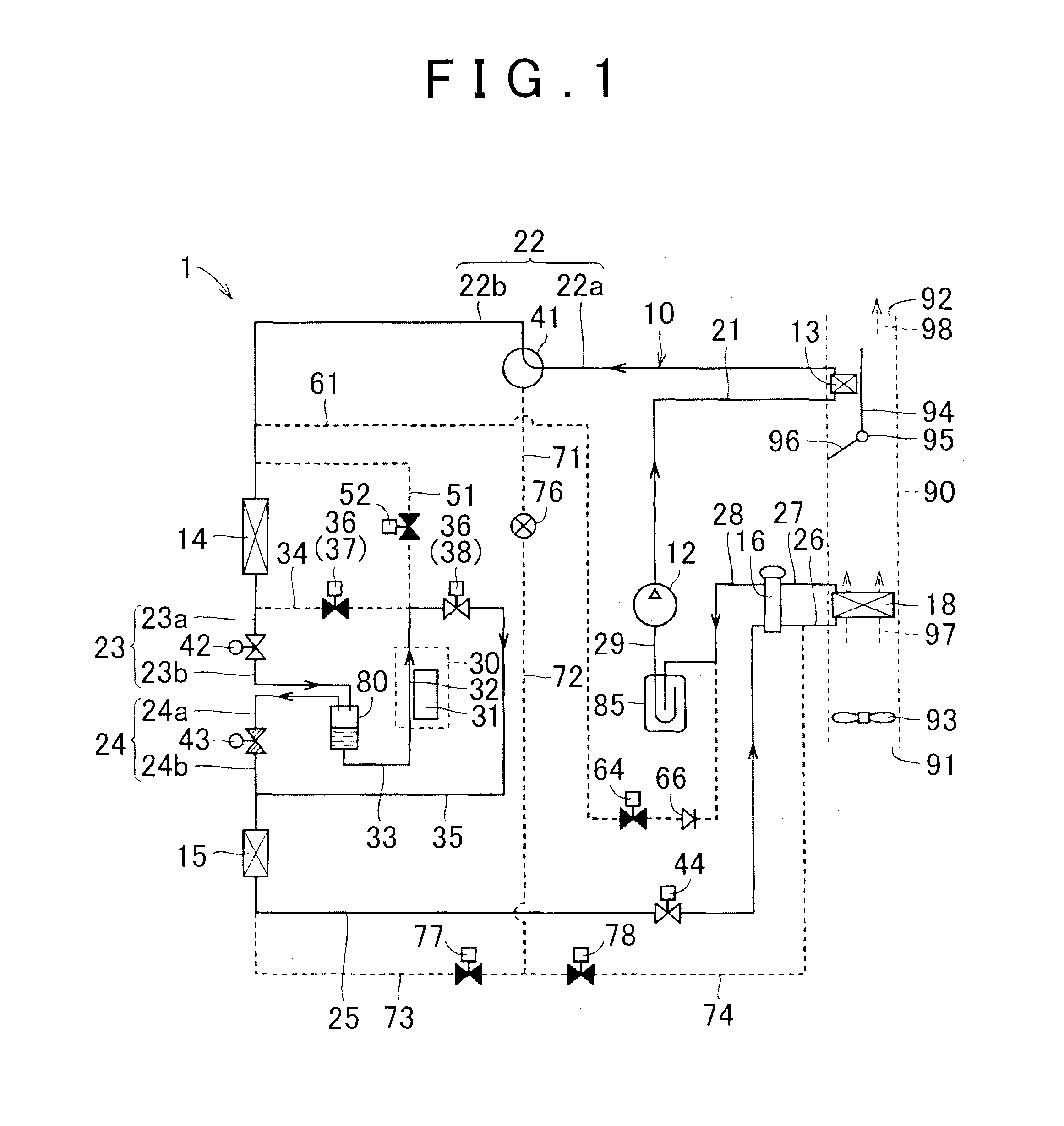
[0030]FIG. 1 is a schematic view that shows the configuration of a cooling system 1. As shown in FIG. 1, the cooling system 1 includes a vapor compression refrigeration cycle 10. The vapor compression refrigeration cycle 10 is, for example, mounted on a vehicle in order to cool or heat the cabin of the vehicle. Cooling using the vapor compression refrigeration cycle 10 is performed, for example, when a switch for cooling is turned on or when an automatic control mode in which the temperature in the cabin of the vehicle is automatically adjusted to a set temperature is selected and the temperature in the cabin is higher than the set temperature. Heating using the vapor compression refrigeration cycle 10 is ...


PUM


Abstract

A three-way valve switches between flow of refrigerant from a heat exchanger toward a cooling portion via a gas-liquid separator and flow of refrigerant from a heat exchanger toward the cooling portion via the gas-liquid separator. A refrigerant line provides fluid communication between the heat exchanger and the gas-liquid separator. A refrigerant line provides fluid communication between the heat exchanger and the gas-liquid separator. A selector valve switches between flow of refrigerant from the cooling portion toward the heat exchanger via a refrigerant line and flow of refrigerant from the cooling portion toward the heat exchanger via a refrigerant line.

Description

BACKGROUND OF THE INVENTION[0001]1. Field of the Invention[0002]The invention relates to a cooling system and, more particularly, to a cooling system that cools a heat generating source by utilizing a vapor compression refrigeration cycle.[0003]2. Description of Related Art[0004]As for an existing vehicle air-conditioning system, for example, Japanese Patent Application Publication No. 5-96940 (JP 5-96940 A) describes an air-conditioning system that includes an interior air heat exchanger and that is able to carry out heating mode operation and cooling mode operation with the use of a four-way valve.[0005]In recent years, hybrid vehicles, fuel cell vehicles, electric vehicles, and the like, that run with driving force of a motor become a focus of attention as one of measures against environmental issues. In such vehicles, electrical devices, such as a motor, a generator, an inverter, a converter and a battery, exchange electric power to generate heat. Therefore, these electrical dev...

Claims


Application Information

Patent Timeline
IPC IPC(8): B60H1/00
CPCB60H1/00271B60H1/00278B60H1/00899B60H2001/00307B60H2001/00949F25B2400/23F25B2600/2507F25B41/20F25B41/24
Inventor OHNO, YUICHIUCHIDA, KAZUHIDEKAWAKAMI, YOSHIAKI
Owner TOYOTA JIDOSHA KK
Why Eureka
Try Eureka