

Light emitting panel and method for manufacturing same
a technology of light emitting panels and manufacturing methods, applied in the direction of sustainable manufacturing/processing, final product manufacturing, thermoelectric devices, etc., can solve the problems of low yield, degraded brightness distribution, and incorporation into lighting equipmen
- Summary
- Abstract
- Description
- Claims
- Application Information
AI Technical Summary
Benefits of technology
Problems solved by technology
Method used
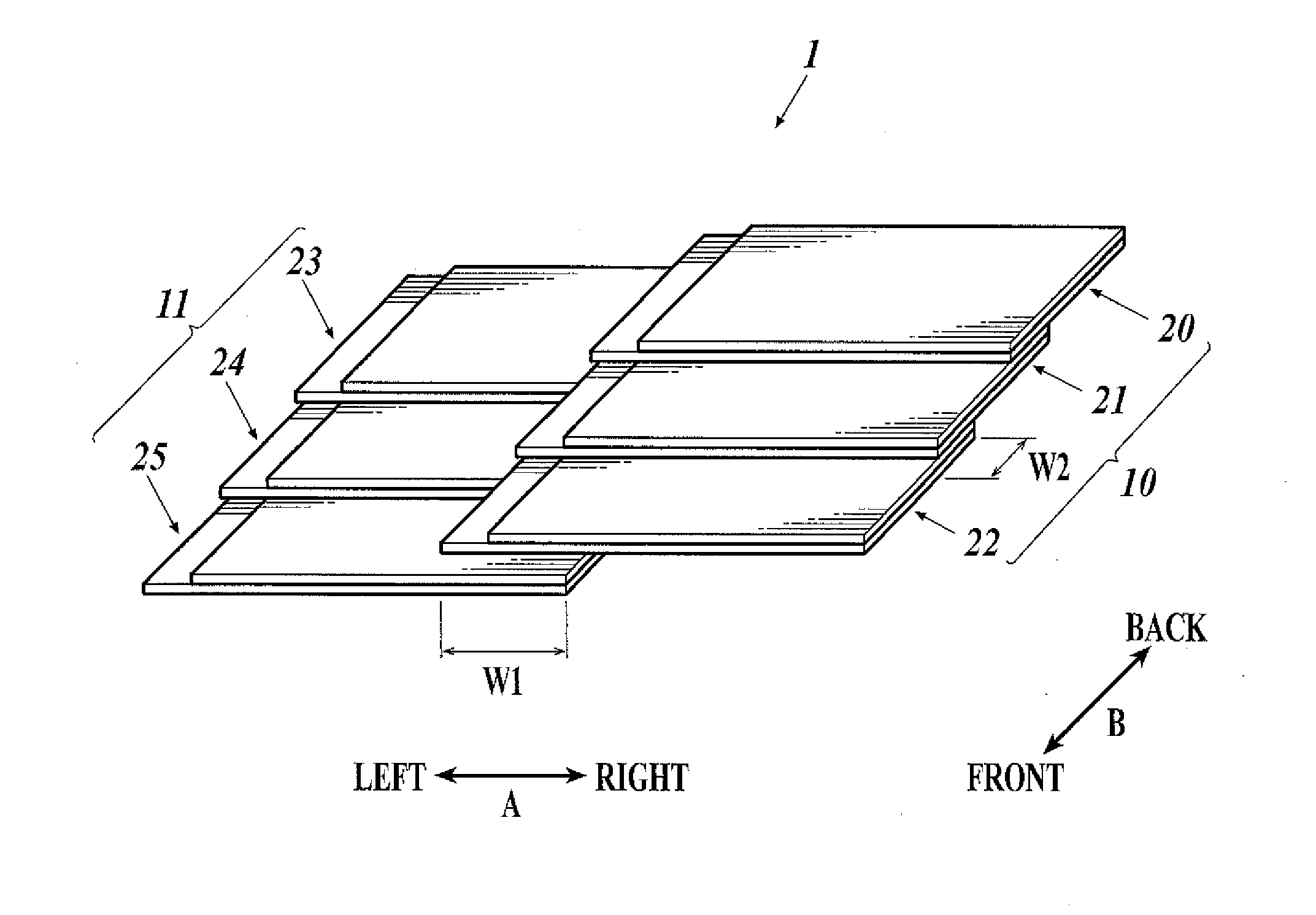
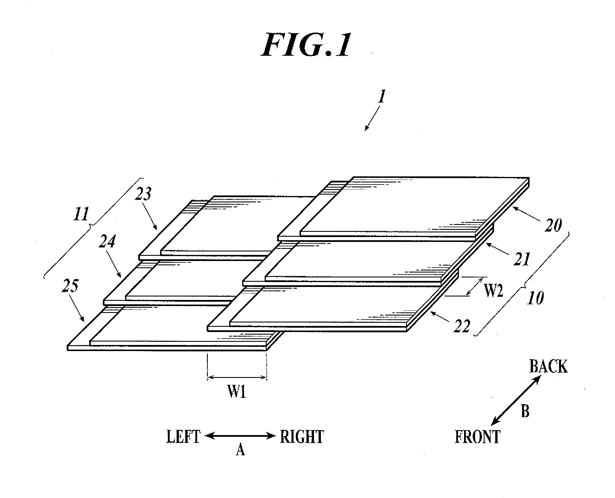
Image

Examples
example 1
(1) Manufacture of Light Emitting Panel 1-1
[0134]As the transparent support substrate, a transparent glass substrate (EAGLE XG (alkali-free glass), Corning Inc.) having a thickness of 0.7 mm and a size of 66 mm×175 mm was prepared. On the substrate, an ITO film was formed to a thickness of 150 nm as the positive electrode.
[0135]After being patterned by a photolithography process, the substrate with the ITO film was subject to ultrasonic cleaning in isopropyl alcohol, was dried in dry nitrogen gas, and was subject to UV ozone cleaning for 5 minutes.
[0136]Next, as the hole injecting layer, CLEVIOS P VP A14083 (Heraeus Clevios Co.) was applied on the substrate using a commercial spin coater so that the dried film thickness becomes 30 nm.
[0137]Thereafter, the substrate was heated at 200° C. in the air for 1 hour.
[0138]Next, the transparent substrate, on which the hole injecting layer had been formed, was fixed on a substrate holder of a vacuum deposition apparatus, and a deposition mask...
example 2
(1) Manufacture of Light Emitting Panel 2-1
[0165]As illustrated in FIG. 26, a light emitting panel 2-1 was manufactured in the same manner as the light emitting panel 1-1 except that double-layered 0.7 mm thick alkali free glass plates 72 were inserted and bonded in the spaces 4 and 4 as spacers.
(2) Manufacture of Light Emitting Panel 2-2
[0166]A light emitting panel 2-2 was manufactured in the same manner as the light emitting panel 2-1 except that the sealing members (method) and the spacers were changed as follows.
[0167]As each of the sealing members, a 0.7 mm thick alkali free glass (EAGLE XG, Corning Inc.) was cut into 66×167 mm, and was subjected to ultrasonic cleaning in isopropyl alcohol. Thereafter, the glass was dried in dry nitrogen gas, and was further subjected to UV ozone cleaning for 5 minutes.
[0168]Then, thermoset adhesive (sealer) was evenly applied on one face of the cleaned sealing member by using a dispenser. The sealing members were thus manufactured. For the the...
example 3
(1) Manufacture of Light Emitting Panel 3-1
[0180]A light emitting panel 3-1 was manufactured in the same manner as the light emitting panel 2-1 except that the support substrates, the sealing members (method) and the spacers were changed as follows.
[0181]As each of the transparent substrates, a transparent glass substrate (alkali free glass, Nippon Electric Glass Co., Ltd.) having a thickness of 0.2 mm and a size of 66×175 mm was used.
[0182]As each of the sealing members, a polyethylene naphthalate substrate (PEN substrate) (TEONEX Q83, Teijin DuPont Films Japan Ltd.) having a thickness of 125 μm and a size of 66×167 mm was prepared. On the PEN substrate, an inorganic gas barrier film of SiOx (500 nm thick) was formed by using an atomospheric-pressure plasma discharge processing apparatus that had a configuration as disclosed in Japanese Patent Unexamined Publication No. 2004-68143. In this way, a polyethylene naphthalate film having a gas barrier property of an oxygen permeability ...
PUM
 Abstract
Description
Claims
Application Information