Roof construction for a motor vehicle and motor vehicle bodyshell

a technology for motor vehicles and roofs, applied in the direction of roofs, mechanical equipment, transportation and packaging, etc., can solve the problems of increasing the complexity of mounting the same at the roof construction of the vehicle, and achieve the effect of increasing the rigidity of the connection of the transverse stru

Inactive Publication Date: 2015-01-29
DAIMLER AG
View PDF9 Cites 11 Cited by
  • Summary
  • Abstract
  • Description
  • Claims
  • Application Information

AI Technical Summary

Benefits of technology

[0006]Preferably, it is provided that the two roof modules are bonded to the transverse strut. In this way, a tight connection between the roof modules and the transverse strut can be achieved with little effort.
[0009]According to one embodiment of the invention it is provided that the transverse strut includes two bearing surfaces for the roof modules, wherein the bearing surface associated to the sliding roof module is arranged at a lower level than the bearing surface associated to the further roof module. This configuration takes into account that the sliding roof module usually is constructed higher in vertical direction than the further roof module, in particular when the same is designed as stationary pane. The bearing surfaces arranged at different heights provide for mounting the roof modules directly at the transverse strut, without having to create a separate, module-side height compensation.
[0010]According to a preferred embodiment of the invention, the transverse strut is designed as box section which is composed of four individual segments which provide the transverse strut with a high rigidity in z-direction. The strength in particular is so high that the transverse strut can absorb the forces acting in z-direction during bonding of the roof modules, without having to separately support the same. The forces occurring during assembly and in particular during bonding of the roof modules are very much higher than those which occur during operation of the motor vehicle.
[0013]According to a preferred embodiment of the invention it is provided that the transverse strut each is provided with a gusset plate at its lateral ends. The gusset plate provides for designing the connection between the transverse strut and the vehicle body with a particularly high strength.
[0014]Preferably, it is provided that a rear swing-out mechanism of the sliding roof module is mounted at the transverse strut and in particular at the gusset plate. This construction leads to a particularly high rigidity of the rear swing-out mechanism, so that the lid of the sliding roof module is stiffly supported also in the open condition. This provides for using a short support length for the lid in the open condition, whereby a large roof opening can be realized.
[0016]According to one aspect of the invention it is provided that the transverse strut is provided with welding lugs which are welded to the roof construction of the bodyshell. This variant additionally increases the rigidity of the connection of the transverse strut with the bodyshell, in particular when the welding lugs are provided in addition to the gusset plates.

Problems solved by technology

The more functions the individual roof modules have, the more complicated does it become to mount the same at the roof construction of the vehicle.

Method used


Image

  • Roof construction for a motor vehicle and motor vehicle bodyshell
  • Roof construction for a motor vehicle and motor vehicle bodyshell
  • Roof construction for a motor vehicle and motor vehicle bodyshell

Examples


Embodiment Construction

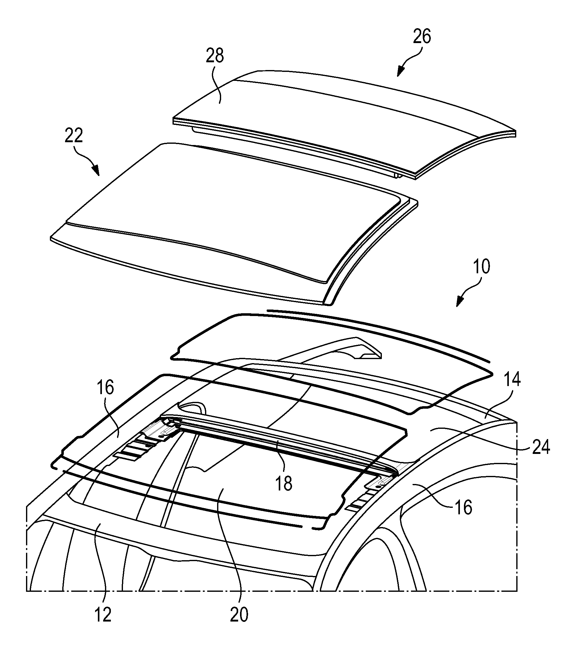
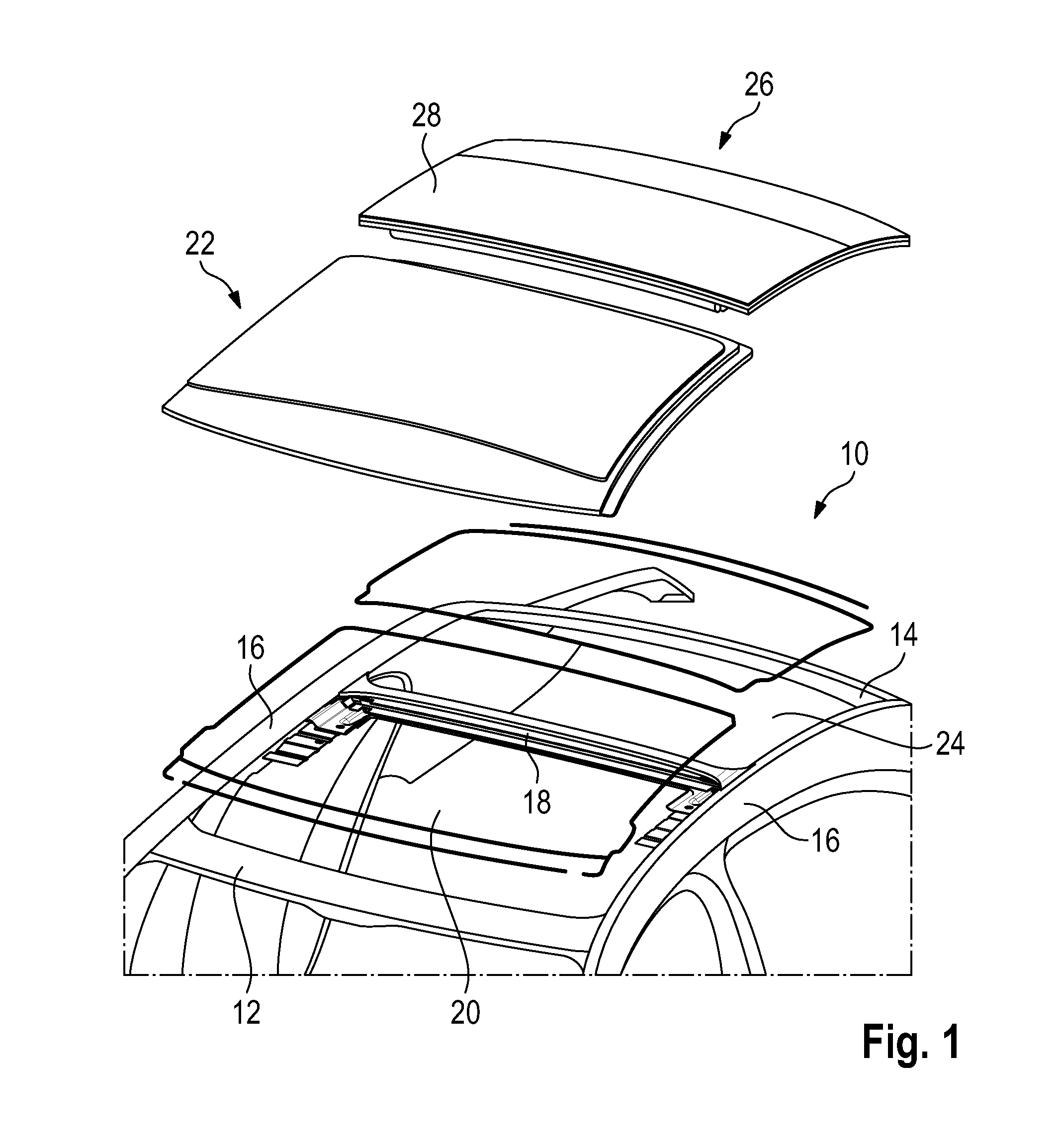
[0027]FIG. 1 schematically shows a roof construction 10 which contains a front crossbeam 12, a rear crossbeam 14, two roof rails 16 extending in longitudinal direction, and a transverse strut 18. The beams 12, 14, 16 and the transverse strut 18 belong to a bodyshell of a motor vehicle.

[0028]Between the front crossbeam 12 and the transverse strut 18 as well as the corresponding portions of the two longitudinal beams 16 a front roof opening 20 is formed, to which a first roof module 22 is associated. The roof module 22 is designed as sliding roof module.

[0029]Between the transverse strut 18 and the rear crossbeam 14 as well as the corresponding portions of the longitudinal beams 16 a rear roof opening 24 is defined, to which a second roof module 26 is associated. This roof module here is designed with a stationary lid 28 which is transparent.

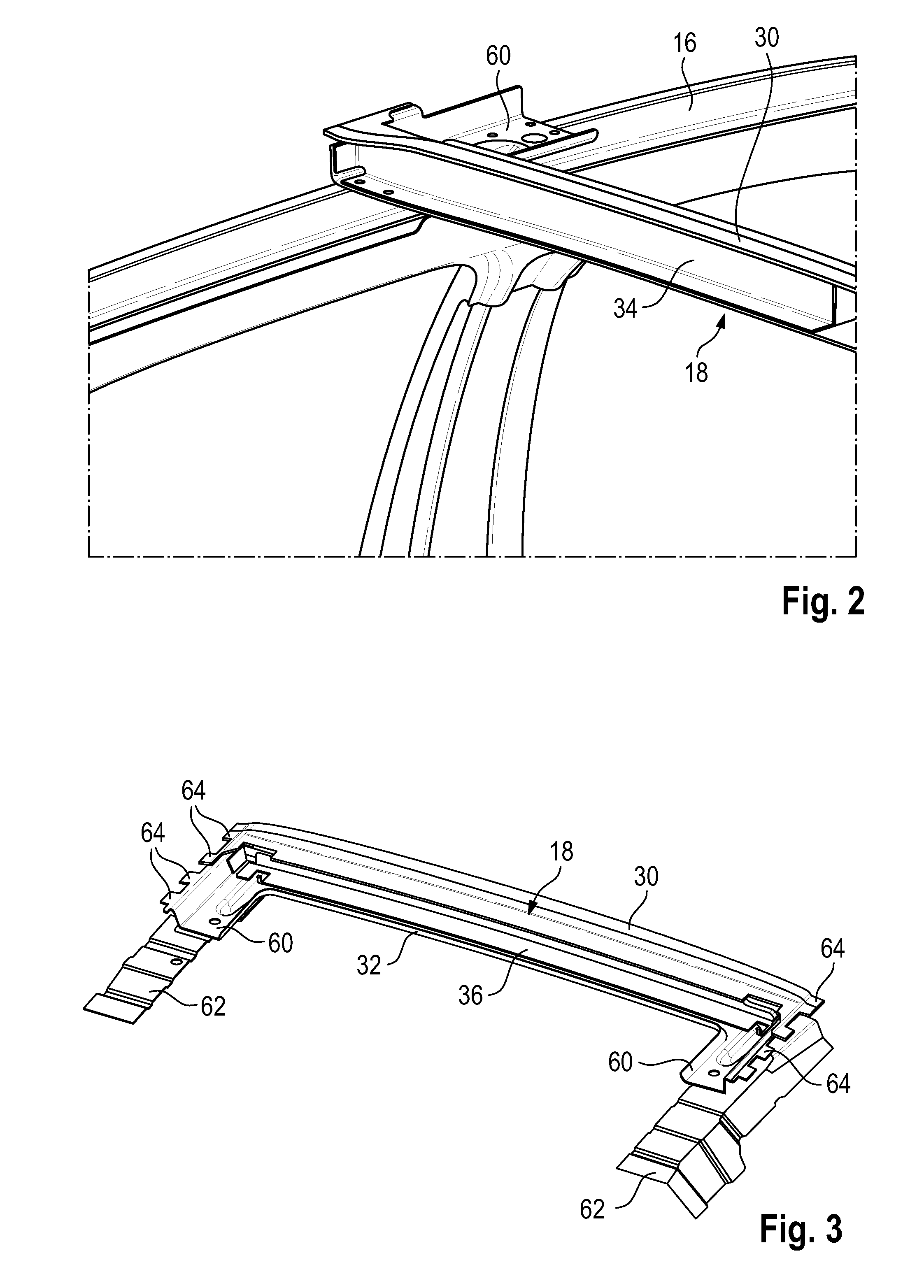
[0030]The transverse strut 18 is a composite component which in the middle part is composed of a total of four individual parts (see in particula...


PUM


Abstract

There is provided a roof construction with a sliding roof module and at least one further roof module, wherein between the sliding roof module and the roof module a transverse strut is arranged, which is part of a vehicle body, wherein an edge portion of the sliding roof module and an edge of the roof module are connected with the transverse strut and between the two roof modules a water channel is formed.

Description

CROSS REFERENCE TO RELATED APPLICATIONS[0001]This application claims priority under 35 U.S.0 §119 to the following German Patent Application No. DE 10 2013 108 081.2 filed on Jul. 29, 2013, the contents of which are incorporated herein by reference thereto.BACKGROUND[0002]The invention relates to a roof construction with a sliding roof module and at least one further roof module.[0003]In motor vehicles several roof modules frequently are mounted at the roof construction, for example the sliding roof module and the further roof module. The sliding roof module contains a lid which proceeding from a closed position can be opened partly or completely, so that fresh air flows into the vehicle interior. The further roof module can be formed stationary, for example as a large-surface pane, or also in the form of a second sliding roof module which in turn is provided with a lid.[0004]The more functions the individual roof modules have, the more complicated does it become to mount the same a...

Claims


Application Information

Patent Timeline
Patent Type & Authority Applications(United States)
IPC IPC(8): B60J7/047B60J10/12B60J7/00B60J10/82
CPCB60J7/047B60J10/12B60J7/0084B60J7/0015B60J7/0435B60J10/82
Inventor GRIMM, RAINERMONDELLO, CARMELO
Owner DAIMLER AG
Why Eureka
Try Eureka