transformer

Inactive Publication Date: 2015-01-29
DELTA ELECTRONICS INC
View PDF9 Cites 2 Cited by
  • Summary
  • Abstract
  • Description
  • Claims
  • Application Information

AI Technical Summary

Benefits of technology

[0007]The present invention provides a transformer, in which the structural strength of

Problems solved by technology

As known, during operations of the transformer, the magnetic core assembly and the winding coils are readily suffered from magnetic vibration.
Due to the resonance phenomenon, undesired noise is generated.
However, after the gluing material is baked, the volume of the gluing material is expanded to result in stress.
Due to the stress, the middle posts of the two magnetic parts are readily suffered

Method used


Image

  • transformer
  • transformer
  • transformer

Examples


Embodiment Construction

[0015]The present invention will now be described more specifically with reference to the following embodiments. It is to be noted that the following descriptions of preferred embodiments of this invention are presented herein for purpose of illustration and description only. It is not intended to be exhaustive or to be limited to the precise form disclosed.

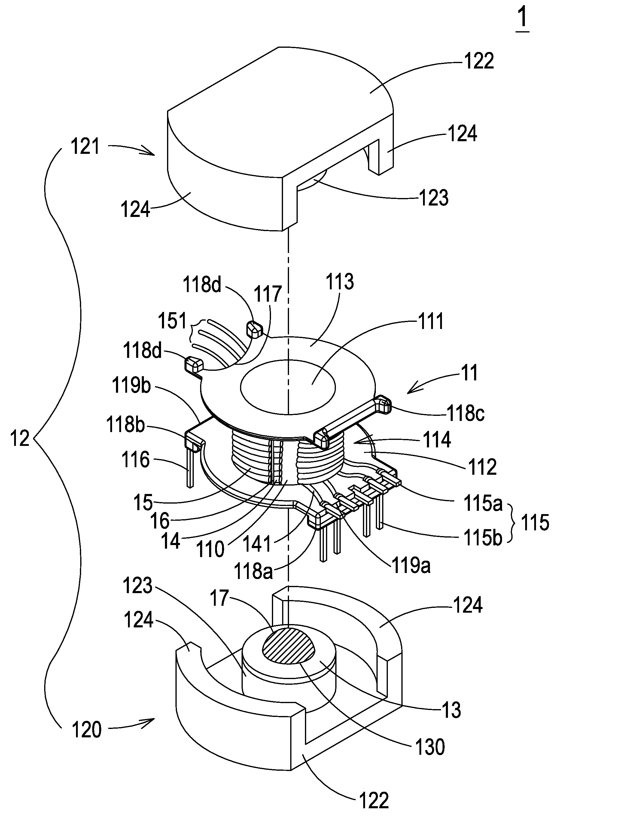
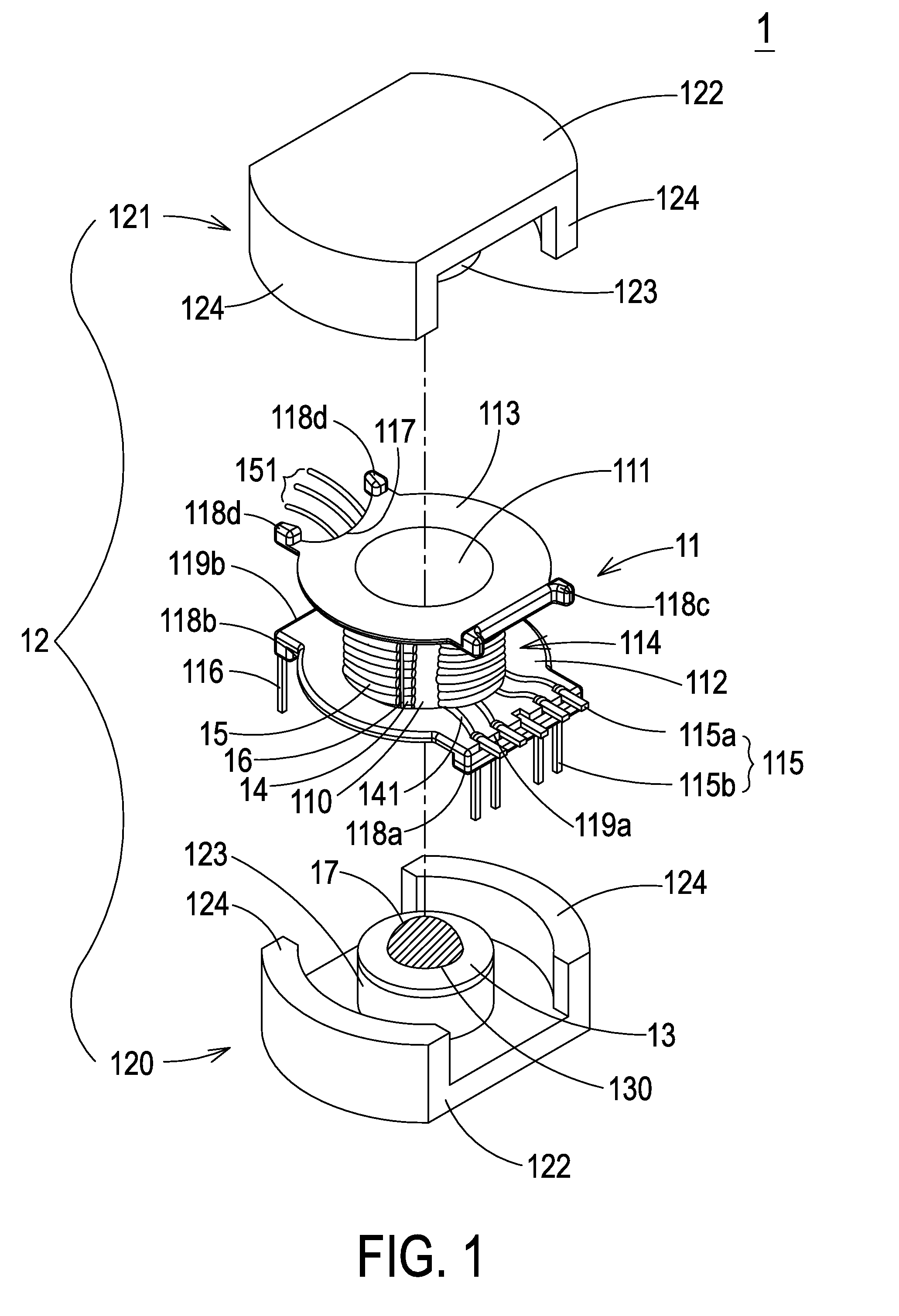
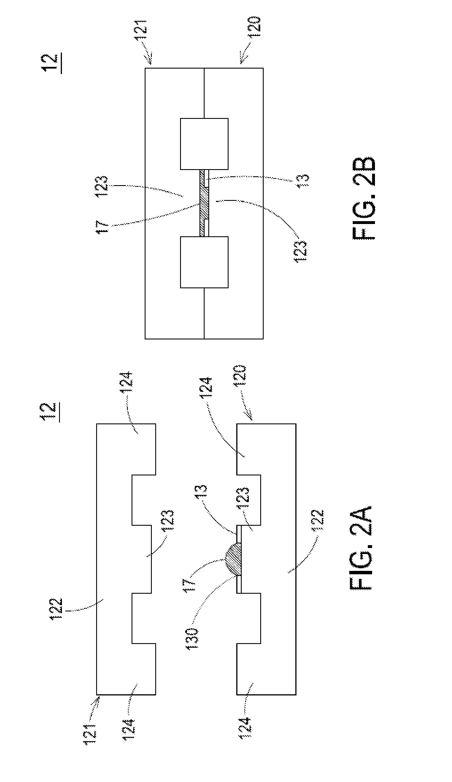
[0016]FIG. 1 is a schematic exploded view illustrating a transformer according to an embodiment of the present invention. As shown in FIG. 1, the transformer 1 comprises a magnetic core assembly 12 and a hollow pad 13. The magnetic core assembly 12 comprises a first magnetic part 120 and a second magnetic part 121. Each of the first magnetic part 120 and the second magnetic part 121 comprises a middle post 123 and two lateral legs 124. The hollow pad 13 is arranged between the middle post 123 of the first magnetic part 120 and the middle post 123 of the second magnetic part 121. The hollow pad 13 has an opening 130 for accommodat...


PUM


Abstract

A transformer includes a magnetic core assembly and a hollow pad. The magnetic core assembly includes a first magnetic part and a second magnetic part. Each of the first magnetic part and the second magnetic part includes a middle post. The hollow pad is arranged between the middle post of the first magnetic part and the middle post of the second magnetic part. The hollow pad has an opening for accommodating a gluing material. The first magnetic part and the second magnetic part are combined together through the gluing material.

Description

CROSS-REFERENCE TO RELATED APPLICATION[0001]This application is a continuation-in-part of U.S. patent application Ser. No. 13 / 779,494, filed on Feb. 27, 2013, and entitled “TRANSFORMER”. The entire disclosures of the above applications are all incorporated herein by reference.FIELD OF THE INVENTION[0002]The present invention relates to a transformer, and more particularly to a transformer with a hollow pad.BACKGROUND OF THE INVENTION[0003]A transformer is a magnetic device that transfers electric energy or magnetic from one circuit to another circuit through coils in order to regulate the voltage to a desired range required for powering an electronic device.[0004]Conventionally, the transformer comprises a bobbin, a magnetic core assembly, a primary winding coil, and a secondary winding coil. The magnetic core assembly comprises two magnetic parts. Each of the tow magnetic parts comprises a middle post and two lateral legs. The two lateral legs are located at bilateral sides of the ...

Claims


Application Information

Patent Timeline
IPC IPC(8): H01F27/26H01F27/33
CPCH01F27/33H01F27/263H01F27/306
Inventor LIN, YU-CHINHUANG, YU-JENZHANG, SHAO-DONGTSAI, CHENG-CHANG
Owner DELTA ELECTRONICS INC
Why Eureka
Try Eureka