
Accurate timing distribution by high-frequency radio

a timing distribution and high-frequency radio technology, applied in the direction of direction finders, scatter propogation systems, instruments, etc., can solve the problems of unreliable hf radio transmission, unstable clocks and portable reference clock signals, and never quite accurate enough to be used in precise timing applications. to achieve the effect of more accurate timing

Active Publication Date: 2015-01-29
MASSACHUSETTS INST OF TECH
View PDF3 Cites 12 Cited by
  • Summary
  • Abstract
  • Description
  • Claims
  • Application Information

AI Technical Summary

Benefits of technology

The patent describes a method and system for transmitting and receiving signals using a polarimetric multichannel receiver for more accurate timing. This method allows for more complex signal transmission and the use of the harmonic relationship of the WWV transmissions to compress the frequency content. This results in a receiver that can continuously receive signals transmitted at all WWV frequencies with a low data rate or low bandwidth processing system. The technical effects of this patent are improved signal accuracy and efficiency in transmitting and receiving signals.

Problems solved by technology

Unfortunately, however, timing information distributed by NIST through transmissions of reference clock signals at WWV in Ft.
Collins, Colo. and WWVH in Kauai, Hi., for example, as well as timing information distributed by other time reference stations, was never quite accurate enough to be used in precise timing applications for reasons that will shortly be discussed.
This is especially true since the infrastructure for distributing timing information by free-running stable clocks and portable reference clock signals is largely no longer in place.
For other applications, however, such are inadequate.
Additionally, there are certain well-known difficulties which make HF radio transmission unreliable when only a single frequency is transmitted.
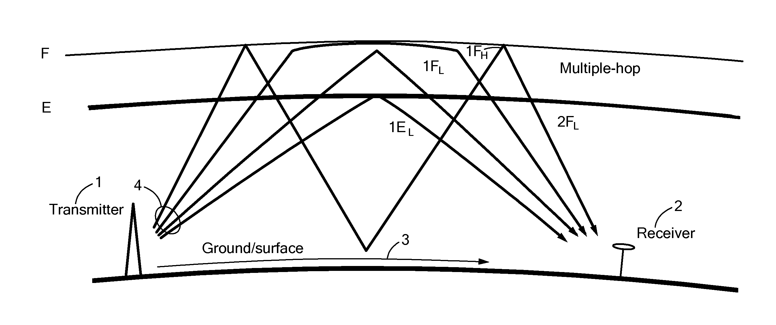
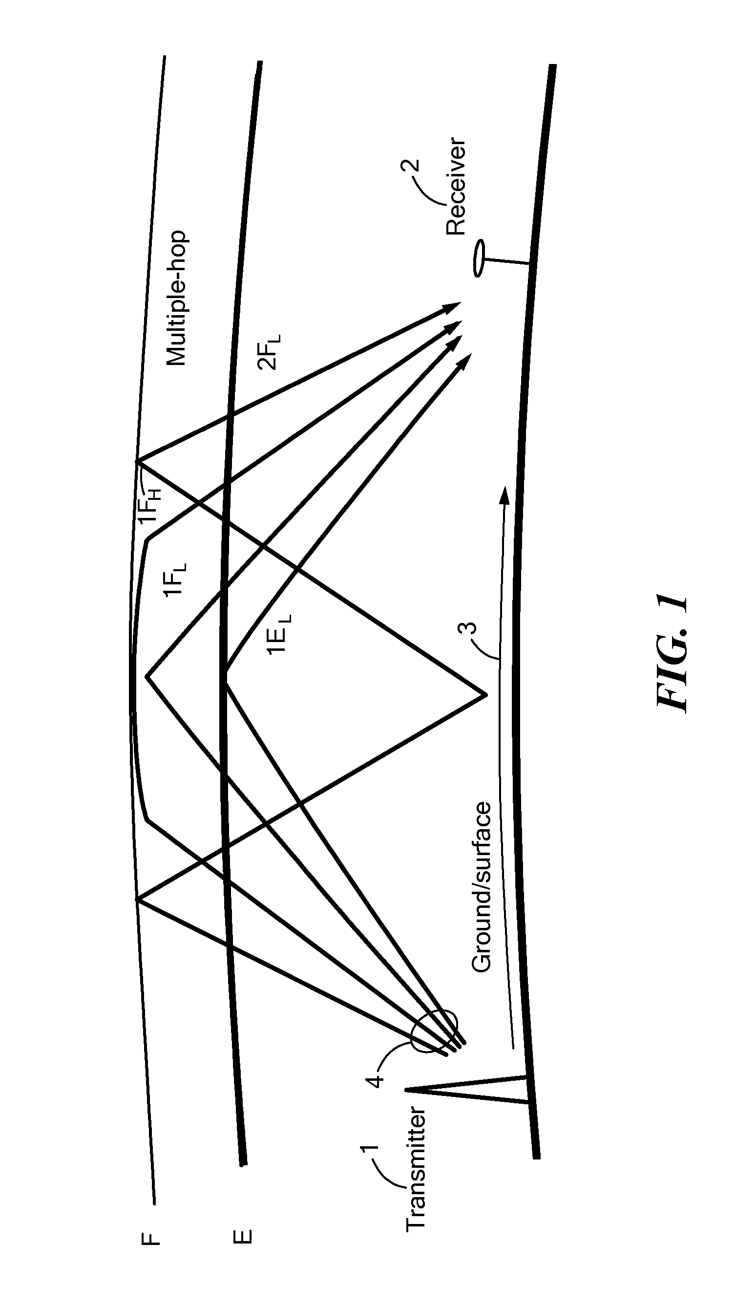
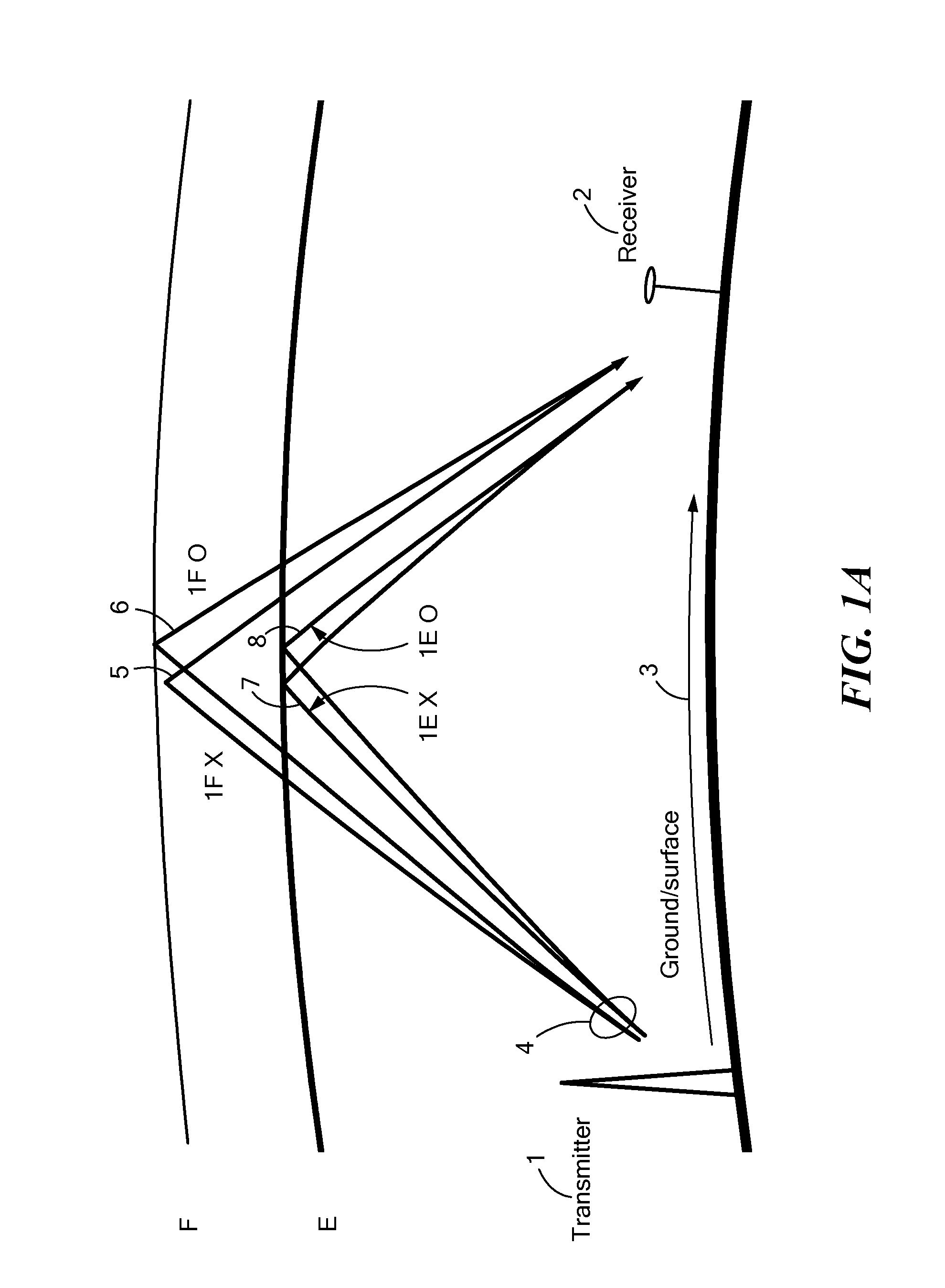
One limitation on distributing accurate timing information from NIST, in addition to the above described issues with the quality of HF signal reception, is largely the uncertainty of the time delay from a transmitter at NIST to a receiver at a second location with the HF signal being “bounced” off of the earth's ionosphere.
Complexities can also arise due to the existence of many potential propagation modes from the transmitter at NIST to the receiver.
Furthermore, the propagation mode and delays associated with each transmission from NIST changes over time.

Method used


Image

  • Accurate timing distribution by high-frequency radio
  • Accurate timing distribution by high-frequency radio
  • Accurate timing distribution by high-frequency radio

Examples


first embodiment

[0043]Referring to FIG. 2A, a flow chart illustrating an example method for determining an absolute time reference according to the first approach described above in conjunction with FIG. 2 is shown. In particular, a transmitter (e.g. a transmitter at NIST) transmits sounding signals and time and frequency reference signals 10 in close time proximity. The time proximity should, for example, occur more rapidly than the changes. However, in certain (unusual) circumstances within several minutes would generally be sufficient. As is known, sounding signals are coded signals conventionally employed for testing and assessing the reception quality of one or more intended receivers and for determining the structure of the ionosphere. Sounding signals, in the present embodiment, are also sent for the purpose of characterizing the propagation delay of the time and frequency reference signals. These sounding signals can, for example, be sent and received on a plurality of different frequencies...

second embodiment

[0046]According to the first approach, the transmitted sounding signals and time and frequency reference signals 10 are augmented to include space weather information in the form of an ionospheric model that is local to a particular NIST station (for example, WWV). Through knowledge of the ionospheric model, an absolute delay can be established from the transmitter to the receiver, thereby improving the accuracy of timing information distributed from NIST. This information can then be processed and expressed as an absolute delay from the transmitter to the receiver. With the absolute delay, the timing and frequency information transmitted by WWV can be used at the receiver to compensate the timing to form an absolute time reference 70. An ionospheric model may be determined through various ionosphere parameterizations. For example, the ionosphere may be characterized through ionosphere layer heights and thickness.

[0047]In another embodiment, information from both space weather infor...


PUM


Abstract

A method of obtaining an absolute time reference for a high-frequency (HF) sounding signal includes transmitting a reference signal at a first location and transmitting a sounding signal in close proximity to the transmitting of the reference signal at the first location. The method additionally includes receiving the reference signal at a second location and receiving the sounding signal at the second location. The method further includes determining a relative delay at the second location of the sounding signal in relation to the reference signal. The method also includes determining a propagation mode based upon the relative delay. The method additionally includes determining an absolute time reference based upon the propagation mode being observed. Additional methods and associated systems for implementing the methods are also provided.

Description

CROSS REFERENCE TO RELATED APPLICATION[0001]This application claims the benefit under 35 U.S.C. §119(e) of provisional application Ser. No. 61 / 858,817, entitled “ACCURATE TIMING DISTRIBUTION BY HF RADIO,” filed Jul. 26, 2013 and also to provisional application Ser. No. 61 / 888,645, entitled “ACCURATE TIMING DISTRIBUTION BY HIGH-FREQUENCY RADIO,” filed Oct. 9, 2013, both applications are hereby incorporated herein by reference in their entireties.GOVERNMENT RIGHTS[0002]This disclosure was made with government support under Contract No. FA8721-05-0002 awarded by the US Air Force. The government has certain rights in this disclosure.FIELD BACKGROUND[0003]As is known in the art, prior to the invent of global positioning satellite (GPS) technology, accurate timing information was distributed by transmitting stable reference clock signals between different transmitter and receiver sites with each site having a stable reference clock free-running between synchronizations. Portable reference...

Claims


Application Information

Patent Timeline
IPC IPC(8): H04B1/7073H04B1/00G01S11/02H04B1/7115
CPCH04B1/7073G01S11/02H04B1/0042H04B1/7115H04B7/22G01S13/0218
Inventor ROBEY, FRANK C.
Owner MASSACHUSETTS INST OF TECH
Learn More