
Optical device utilized in laser projector

a laser projector and optical device technology, applied in projectors, color television details, instruments, etc., can solve the problems of phosphor on the phosphor wheel being deteriorated, the temperature of the wheel may be very high, and the energy carried by the laser light beam is highly intensified

Active Publication Date: 2015-01-29
DELTA ELECTRONICS INC
View PDF5 Cites 38 Cited by
  • Summary
  • Abstract
  • Description
  • Claims
  • Application Information

AI Technical Summary

Benefits of technology

The present invention is a device used in a laser projector to prevent damage to the phosphor wheel caused by high temperatures. It uses a thermal exchanger to cool the air, making it colder than the environment, which improves cooling efficiency. The air flows in a circular pattern, which keeps it cleaner than the outside air, reducing the risk of pollution and dust damage.

Problems solved by technology

However, the energy carried by the laser light beam is highly intensified, and the temperature of the wheel may be very high after a time of receiving the laser light beam.
As a result, the phosphor on the phosphor wheel may be deteriorated which decreases the illuminating efficiency of the phosphor.
Hence, the problem of phosphor deterioration from the high temperatures is becoming increasingly severe.

Method used


Image

  • Optical device utilized in laser projector
  • Optical device utilized in laser projector
  • Optical device utilized in laser projector

Examples


Embodiment Construction

[0024]Reference will now be made in detail to the present embodiments of the invention, examples of which are illustrated in the accompanying drawings. Wherever possible, the same reference numbers are used in the drawings and the description to refer to the same or like parts.

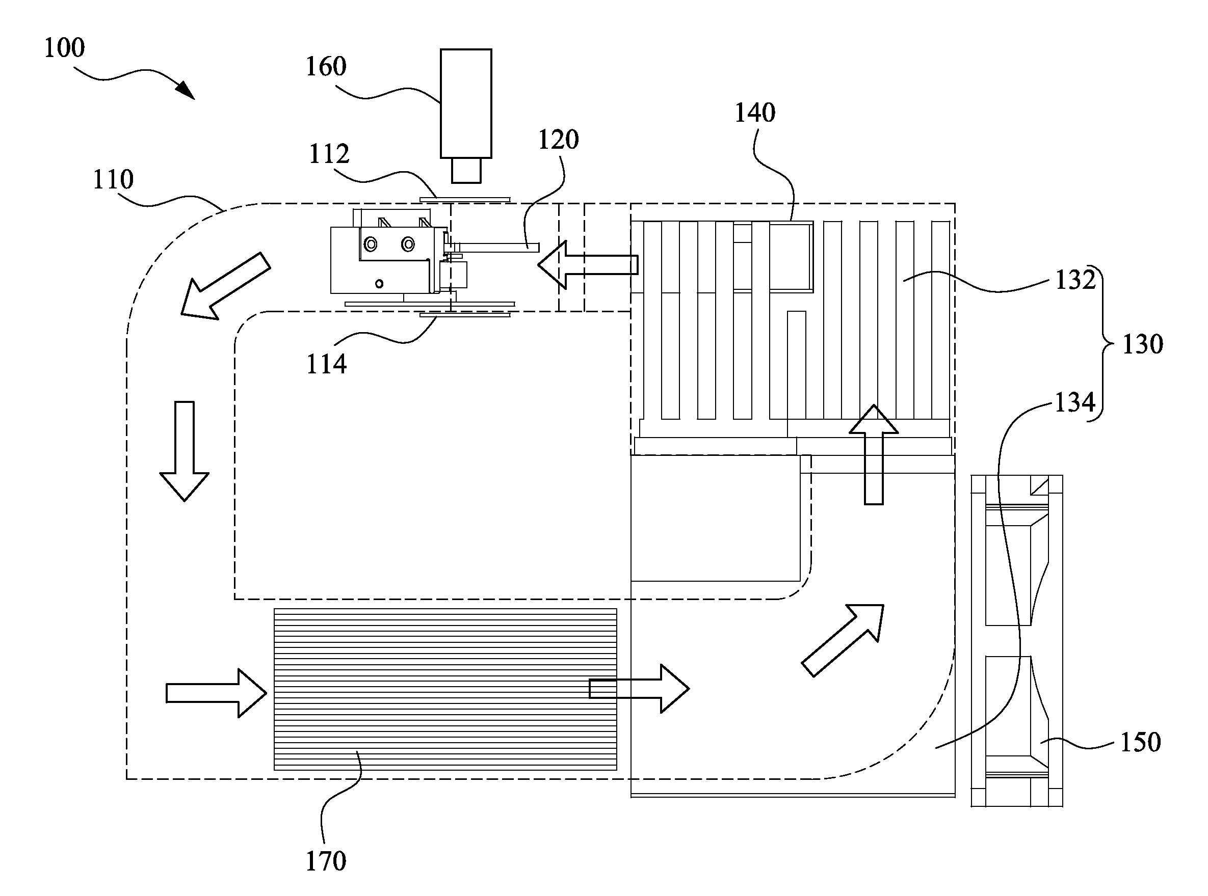
[0025]In order to solve the problem of phosphor wheel being damaged because of the raising temperature due to the high energy carried by the laser beam, a fan is widely used for cooling the phosphor wheel with environment air. However, the cooling efficiency by using only the fan is pretty poor. Therefore, the present invention provides a thermal exchanger and a circulatory air channel for cooling the phosphor wheel with a cold air colder than the environment air thereby improving the heat dissipating efficiency of the phosphor wheel.

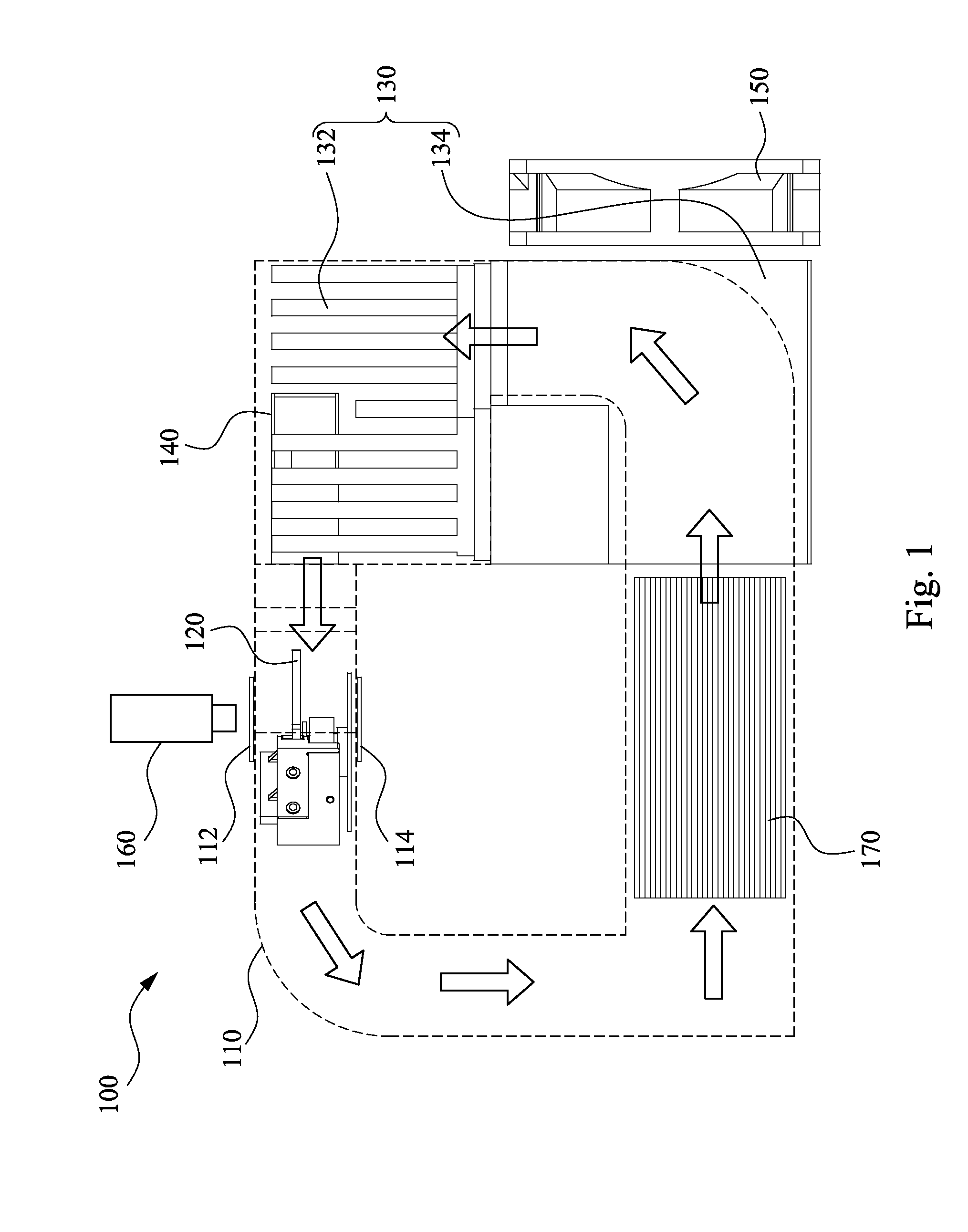
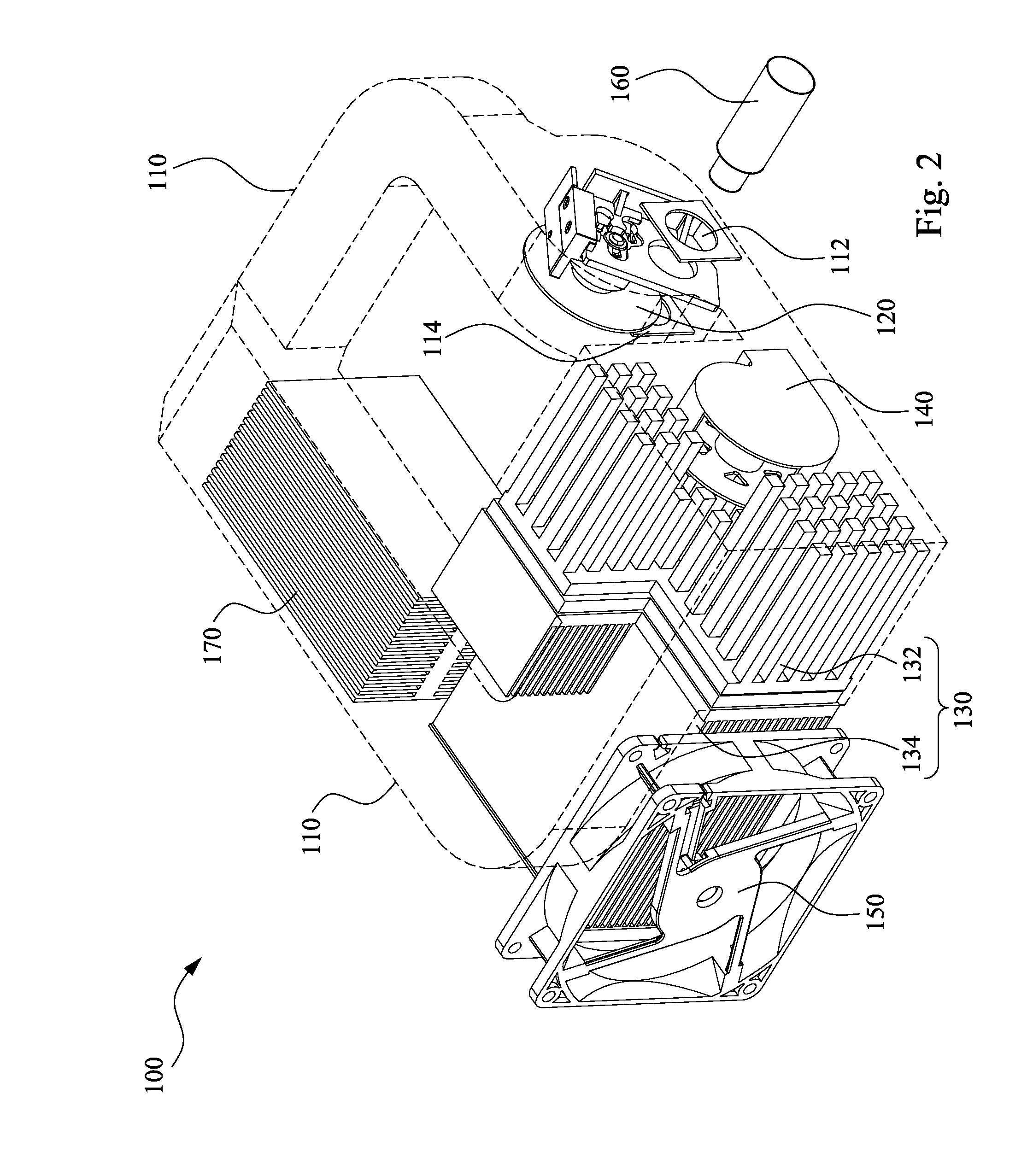
[0026]FIG. 1 is a top view of an embodiment of an optical device utilized in a laser projector of the invention. FIG. 2 is an oblique view of the embodiment of the optical device ...


PUM


Abstract

An optical device utilized in a laser projector includes a circulatory air channel, a phosphor wheel disposed in the circulatory air channel, a thermal exchanger partially disposed in the circulatory air channel, and an air guiding component disposed in the circulatory air channel for guiding an air provided by the thermal exchanger toward the phosphor wheel. The temperature of the air passing through the phosphor wheel is lower than an environment temperature.

Description

RELATED APPLICATIONS[0001]This application claims priority to China Application Serial Number 201320443781.2, filed Jul. 24, 2013, which is herein incorporated by reference.BACKGROUND[0002]1. Field of Invention[0003]The present invention relates to a laser projector. More particularly, the present invention relates to an optical device in the laser projector.[0004]2. Description of Related Art[0005]Optical projectors have been applied in many fields since first being developed. They serve an expanded range of purposes, from use in consumer products to high-tech devices. For example, the optical projectors may be used in projective systems for projecting enlarged images to facilitate presentations given in conferences, or used in projection screens or televisions for projecting and displaying images in real time.[0006]A conventional projector typically includes a light source module and an image processor. The light emitted from the light source module is collected by optical compone...

Claims


Application Information

Patent Timeline
Patent Type & Authority Applications(United States)
IPC IPC(8): G03B21/16
CPCG03B21/16G03B21/2033G03B21/204H04N9/3144H04N9/3158
Inventor LIN, CHIA-JUICHANG, HSIU-MING
Owner DELTA ELECTRONICS INC
Learn More