
Cathode electrode for fuel cell

Active Publication Date: 2015-01-29
NISSAN MOTOR CO LTD
View PDF4 Cites 8 Cited by
  • Summary
  • Abstract
  • Description
  • Claims
  • Application Information

AI Technical Summary

Benefits of technology

The patent aims to provide a cathode electrode for a fuel cell that can improve both the activity of the oxygen reduction reaction (ORR) and the resistance to flooding.

Problems solved by technology

However, if platinum particles are covered with an ionomer, the ORR (Oxygen Reduction Reaction) activity which is inherently possessed by the catalyst particles is not fully expressed, so that performance of the fuel cell has been limited.
Accordingly, this cannot be used in a fuel cell stack especially for the type of high current density.

Method used


Image

  • Cathode electrode for fuel cell
  • Cathode electrode for fuel cell
  • Cathode electrode for fuel cell

Examples


Embodiment Construction

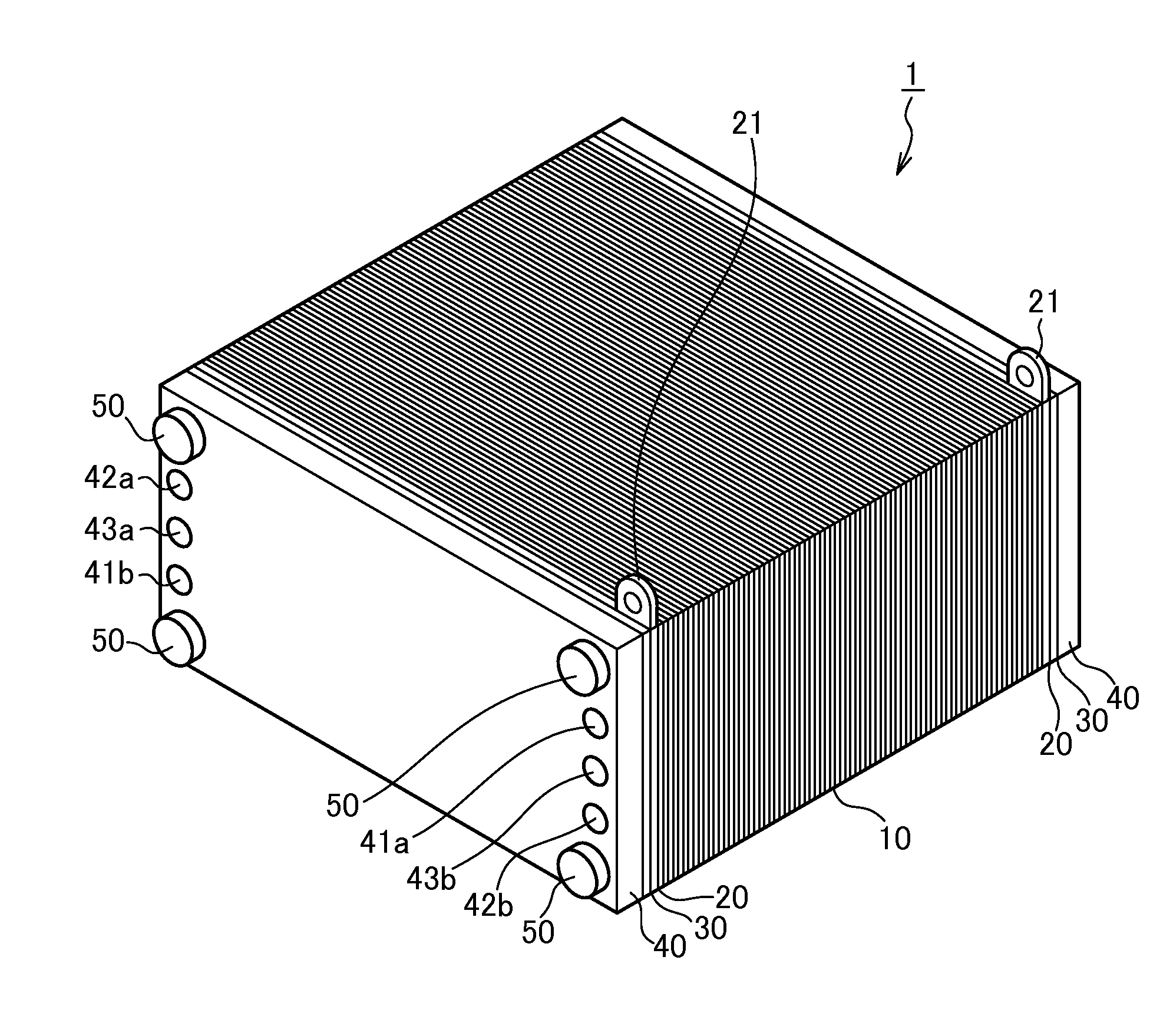
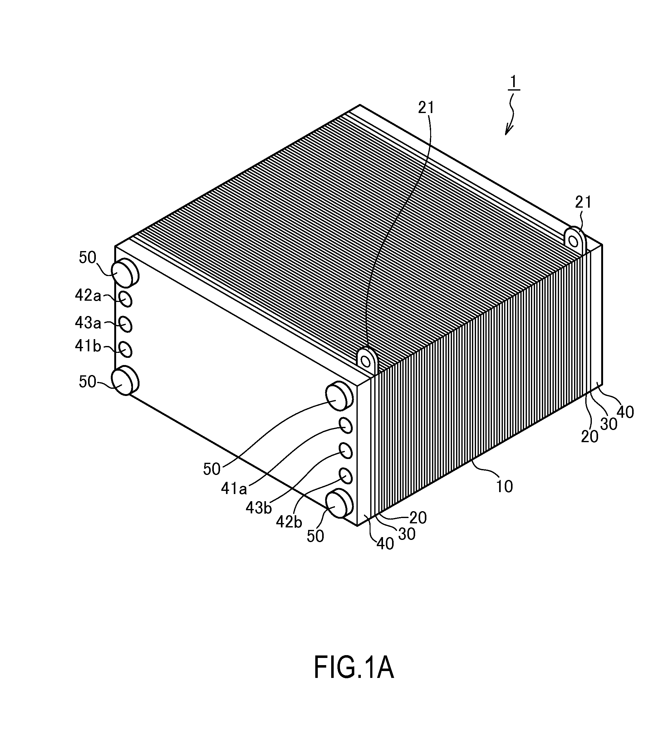
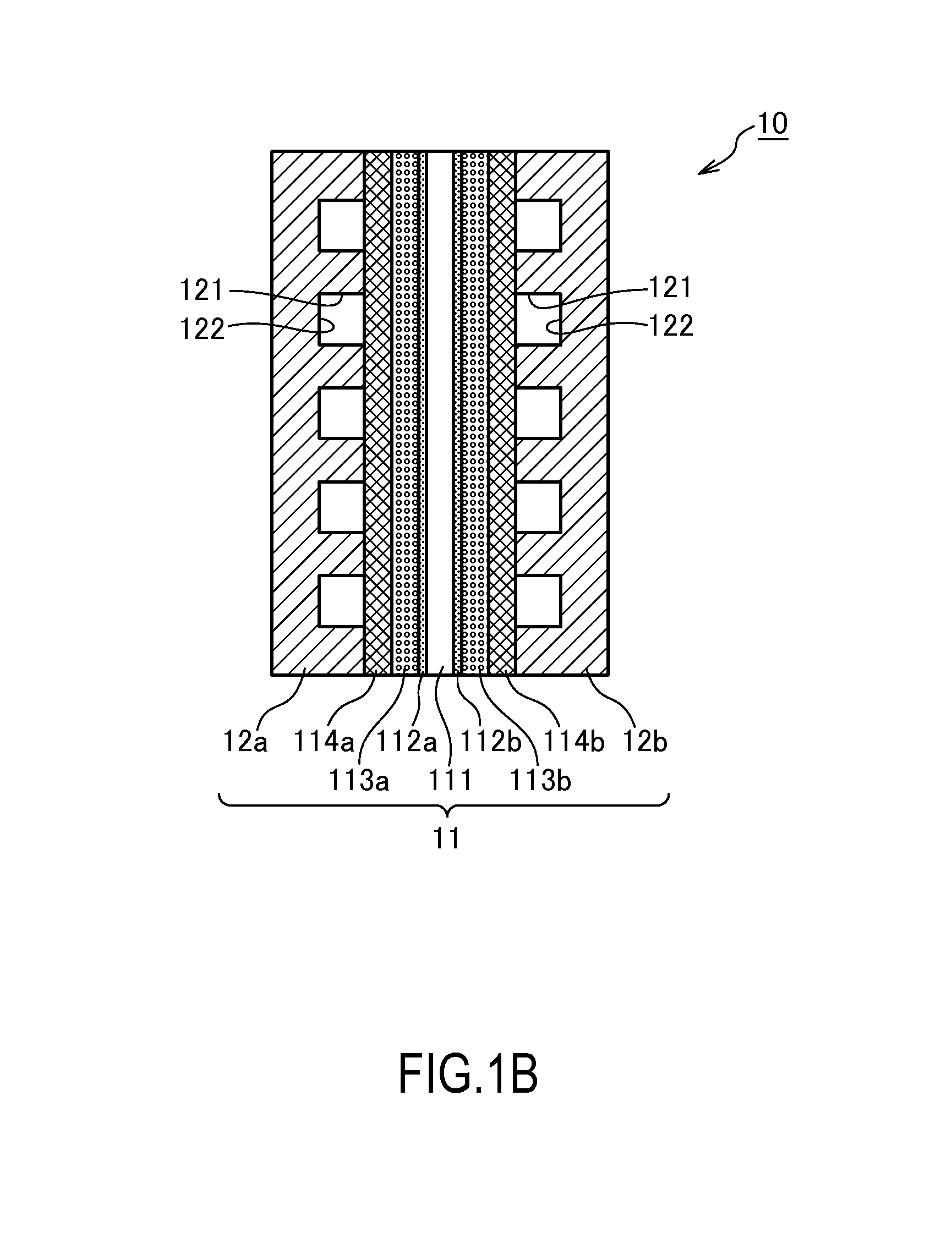
[0016]FIG. 1A and FIG. 1B are drawings to explain the fuel cell to which the cathode electrode for the fuel cell according to the present invention is applied, wherein showing the outer perspective view thereof in FIG. 1A and the enlarged view of the power generating cell thereof in FIG. 1B.

[0017]At first, the basic configuration of the fuel cell is explained by referring to FIG. 1. The fuel cell stack 1 has the stack of a plurality of the power generating cell 10, the current collecting plates 20, the insulating plates 30, the end plates 40, and four tension rods 50.

[0018]The power generating cell 10 is the unit cell of the fuel cell. Each of the power generating cells 10 generates about one volt (V) of the electromotive voltage. Configuration details of each of the power generating cells 10 will be explained later.

[0019]Each of the current collecting plates 20 is placed outside the stack of a plurality of the power generating cells 10, and the current collecting plates 20 are form...


PUM


Abstract

A cathode electrode for a fuel cell, includes a conductive carrier having pores and a catalyst having a platinum alloy supported in the pores of the conductive carrier, wherein the catalyst has in a pore diameter range of 2 to 6 nm when diameters of the pores is plotted in relation with volumes of the pores a peak value of more than 1 cm3 / g and also a BET specific surface area of 1300 m2 / g.

Description

TECHNICAL FIELD[0001]The present invention relates to a cathode electrode for a fuel cell.BACKGROUND ART[0002]There is a prior art reference, WO 2009 / 075264, relating to the present invention.SUMMARY OF INVENTION[0003]In a catalyst carrier (carbon) that have been used from past in a fuel cell, catalyst particles are covered with an ionomer in order to secure transportability of a proton (H+). However, if platinum particles are covered with an ionomer, the ORR (Oxygen Reduction Reaction) activity which is inherently possessed by the catalyst particles is not fully expressed, so that performance of the fuel cell has been limited. On the other hand, in order that the catalyst particles might express their inherently possessing performance, when a catalyst carrier in which the catalyst particles were difficult to be covered by the ionomer was used (such as for example, Ketjen black), flooding tended to occur readily especially in high current density in which large amount of water is ge...

Claims


Application Information

Patent Timeline
IPC IPC(8): H01M4/92H01M8/10H01M4/86
CPCH01M4/921H01M2008/1095H01M8/10H01M4/8605H01M4/926H01M2004/8689Y02E60/50H01M4/86H01M4/92
Inventor SHIMOI, RYOICHITAKAICHI, SATOSHIMIYAZAKI, SHINICHIOKUI, TAKEHIKO
Owner NISSAN MOTOR CO LTD
Learn More