Aerofoil component handling tool

Active Publication Date: 2015-02-05
ROLLS ROYCE PLC
View PDF4 Cites 3 Cited by
  • Summary
  • Abstract
  • Description
  • Claims
  • Application Information

AI Technical Summary

Benefits of technology

The patent describes a handheld tool for removing aerofoils from an array. The tool has a body portion that extends beyond the jaw members, with a levering arm to help remove aerofoils. The body and jaw members may have impact formations to transfer impact force to the tool and dislodge jammed aerofoils. The handle is designed for easy grip and the tool may be made of polymer / plastic material. The technical effects of the tool include improved control and efficiency in removing aerofoils from an array.

Problems solved by technology

Over time, and with prolonged use, aerofoils in such an array have the potential to become damaged, or otherwise need to be removed and / or replaced.
However, due to the high operating temperatures of an axial flow engine and the loading on the aerofoils in use it is possible for aerofoils to become distorted and / or slightly misaligned over time, and this can result in the aerofoils becoming stuck or jammed in their position in the casing channel.
This is a particular problem due the high tolerance required between the stators and the channel.
The force provided by the combination of a hammer or mallet and prying the aerofoil by hand is often insufficient to remove the aerofoil.
This process may need to be repeated a plurality of times, typically using varying impact forces each time, thereby making the process as a whole time-consuming and potentially causing damage to the aerofoils and / or the casing.
Such variations in both success rate and impact forces applied are clearly undesirable for a critical process in the overhaul of a gas turbine engine.
However each of these tools has been found to have associated problems.
Such complex systems are therefore difficult for a fitter to use with any real accuracy.
Such tools often require that an excessive level of force is applied to remove an aerofoil from its position, and this can potentially cause damage to the aerofoil and / or casing, as well as creating potentially hazardous situations for the fitter.
Furthermore, the large scale of such tools can also mean that they are expensive to manufacture.

Method used


Image

  • Aerofoil component handling tool
  • Aerofoil component handling tool
  • Aerofoil component handling tool

Examples


Embodiment Construction

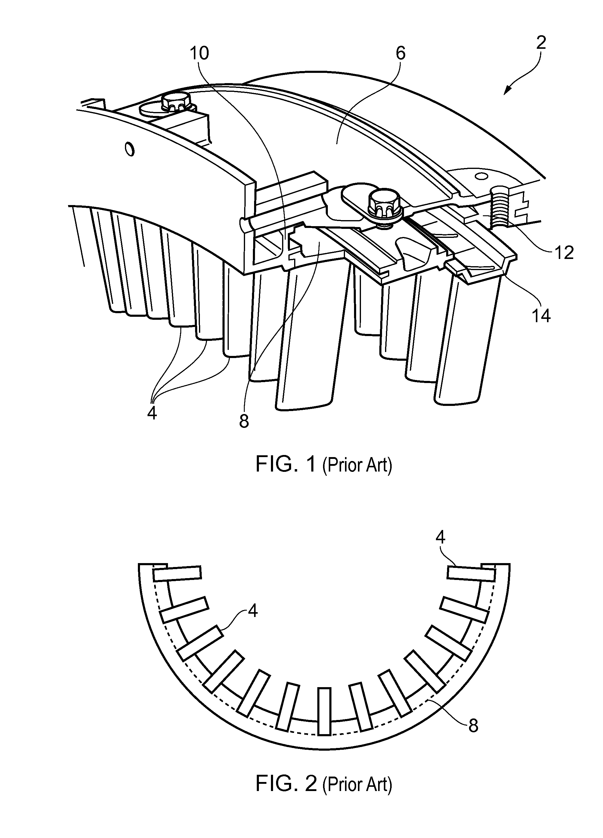
[0054]Referring to FIG. 1, there is shown a portion of a conventional circumferential aerofoil array 2 for a gas turbine engine. The aerofoil array 2 in this example comprises a stator vane array for a compressor. The vanes 4 depend radially inwardly from a casing structure 6 to which the vanes are fixedly attached at their outer ends in use. In particular, the casing 6 is annular in shape and has an elongate recess or channel 8 therein. The channel is annular in form and is defined by opposing side walls 10, 12, which typically comprise a groove, lip or other retaining formation so as to define a slot for holding the vanes 4 securely within the recess (for example, in a radial direction).

[0055]In the example shown, two rows of vanes are provided in a fore and aft arrangement within the annular recess 8. The two rows are held in place by an intermediate retaining ring formation 10, thereby defining two channels within the recess 8. In alternative embodiments, a single channel or rec...


PUM

PropertyMeasurementUnit
Fractionaaaaaaaaaa
Lengthaaaaaaaaaa
Forceaaaaaaaaaa

Abstract

A handheld tool facilitates the removal of an aerofoil from an array of aerofoils for an axial flow machine includes a body portion, and first and second jaw members depending from the body portion. The first jaw member is shaped to be insertable between a first aerofoil and an adjacent aerofoil in the array so as to contact a first surface of the first aerofoil. The position of the first and / or second jaw member is adjustable to selectively grip the aerofoil in use. The second jaw member is adapted to contact a further portion as a trailing edge of the first aerofoil. The tool may allow for manual levering and / or impact forces to be applied to the aerofoil. A method of removal of aerofoils is also provided, involving a sequence of manual operations using the tool. The aerofoil array may be a stator vane array for a gas turbine engine.

Description

BACKGROUND OF THE INVENTION[0001]The present invention relates to axial flow machine assembly / disassembly tools and methods and, in particular, to tools for handling components, such as aerofoils, for overhaul and maintenance of axial flow machines.[0002]In an axial flow machine, a fluid flow is directed along a course that is substantially parallel to an axis of rotation of the machine. An axial flow machine, such as a compressor, impeller, turbine or the like, may form a sub-assembly of a larger machine. The compressor of an axial flow engine is one example of such a machine and typically comprises several axially-aligned stages, with each stage designed to increase the pressure of the airflow passing therethrough. A conventional compressor may thus comprise successive arrays, often referred to as ‘rows’, of aerofoils, typically arranged as successive arrays of rotor blades with each rotor array being spaced by an intermediate array of stator vanes. The purpose of the stator array...

Claims


Application Information

Patent Timeline
IPC IPC(8): F01D5/00
CPCF01D5/005B25B5/068B25B5/14F01D25/285F05D2260/83Y10T29/49318Y10T29/53991B23P6/002B23Q3/063B25B5/02B25B13/12B25B13/50
Inventor BITONDO, DONATOBARTLAM, MARKLEON DE PAZ, MARCEL ERNESTOMACRAE, PETER
Owner ROLLS ROYCE PLC
Why Eureka
Try Eureka