Fiber optic vibration detection

a fiber optic and vibration detection technology, applied in the field of vibration detection, can solve problems such as impaired tunneling detection

Active Publication Date: 2015-02-05
RAYTHEON CO
View PDF11 Cites 16 Cited by
  • Summary
  • Abstract
  • Description
  • Claims
  • Application Information

AI Technical Summary

Benefits of technology

[0006]Although specific advantages have been enumerated above, various embodiments may include some, none, or all of the enumerated advantages. Additio

Problems solved by technology

Tunneling detection is impaired by the large expanses of land to

Method used


Image

  • Fiber optic vibration detection
  • Fiber optic vibration detection
  • Fiber optic vibration detection

Examples


Embodiment Construction

[0015]It should be understood at the outset that, although example embodiments are illustrated below, the present invention may be implemented using any number of techniques, whether currently known or not. The present invention should in no way be limited to the example implementations, drawings, and techniques illustrated below. Additionally, the drawings are not necessarily drawn to scale.

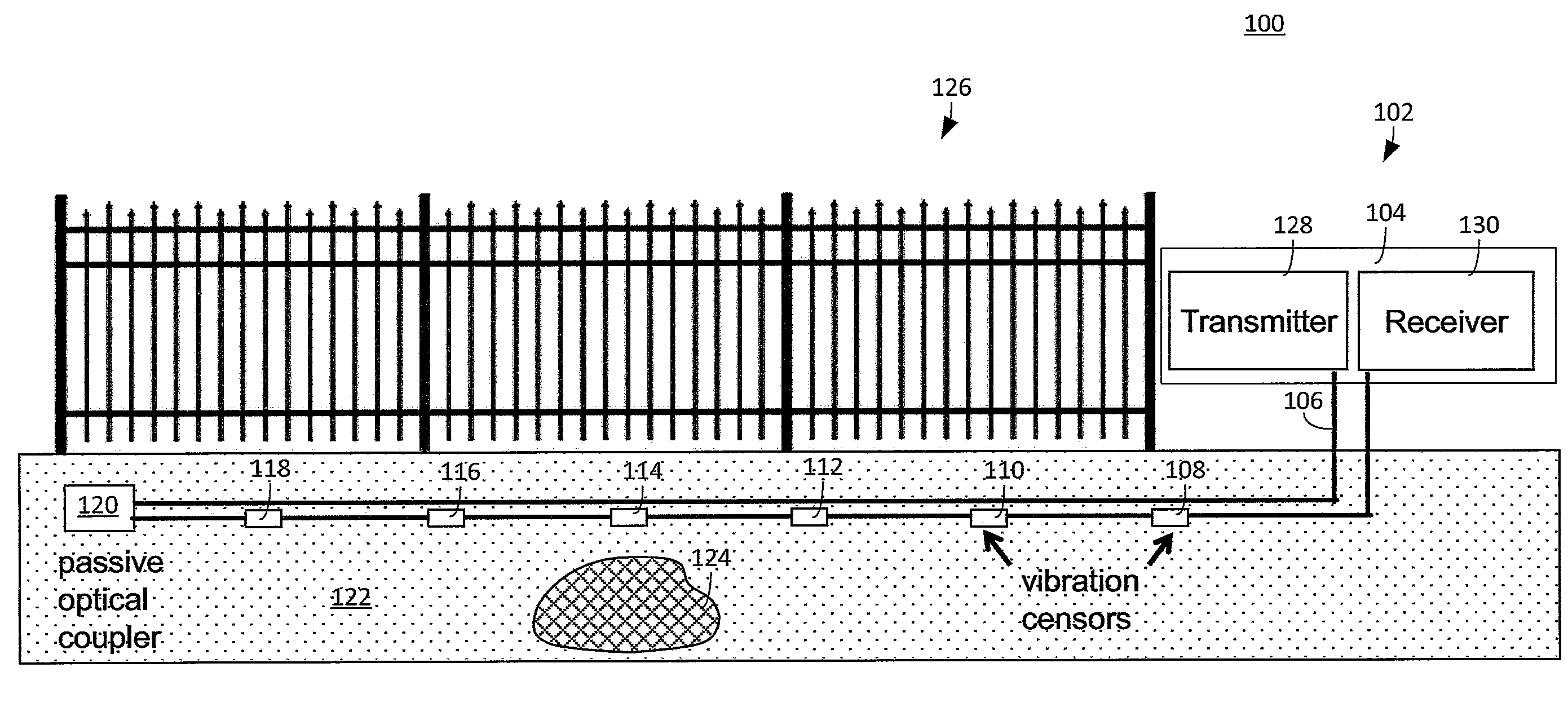
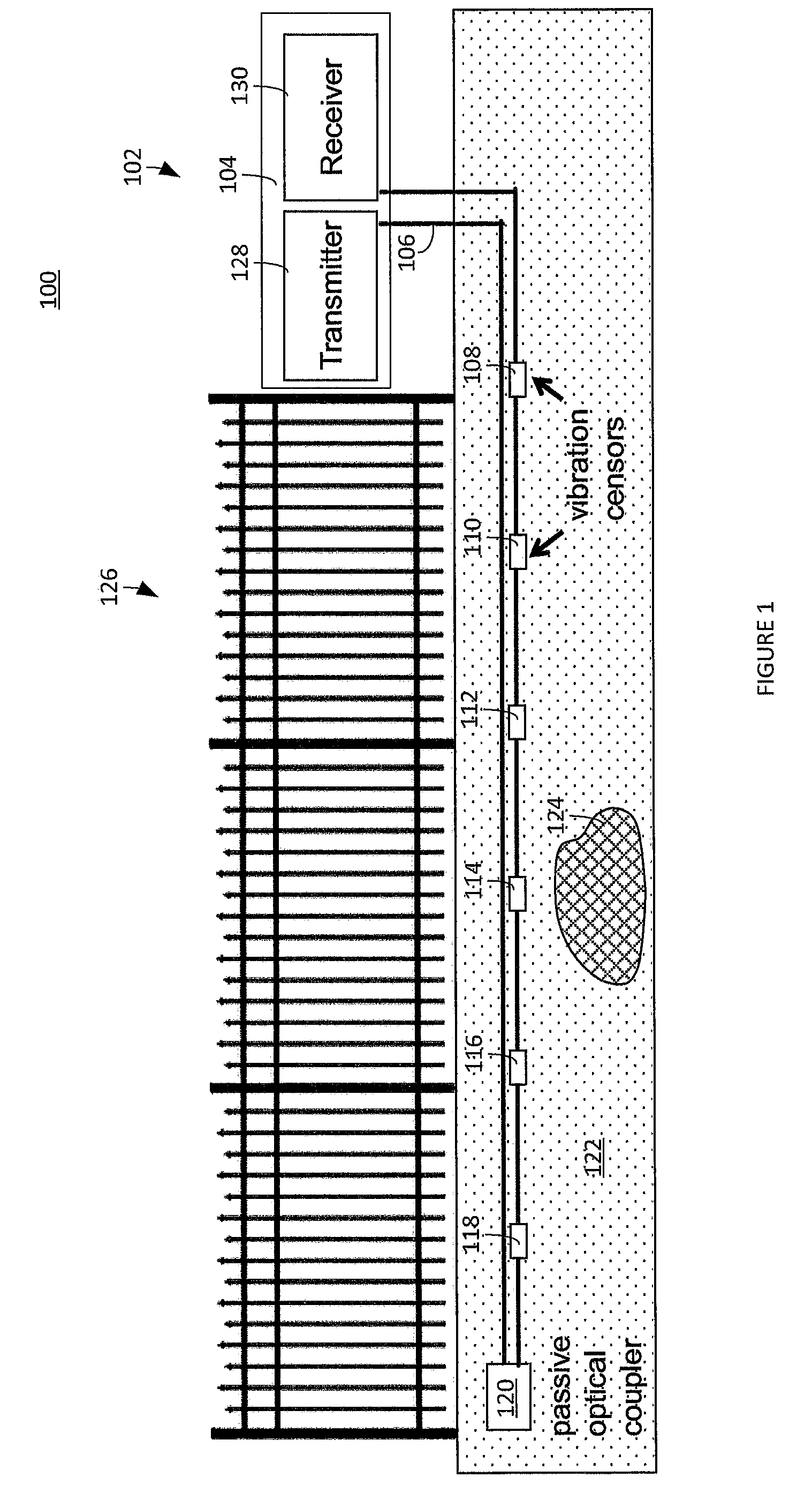
[0016]FIG. 1 illustrates a vibration detection system according to an embodiment of the disclosure. The embodiment illustrated in FIG. 1 is for illustration only. Other embodiments could be used without departing from the scope of this disclosure.

[0017]An environment 100 includes a fence 126, a ground 122, and a tunneling detection system 102. The environment 100 can be a border of a country, a property line of a parcel of land, and the like. The environment 100 is not limited to borders and boundaries and can comprise any portion or expanse of land or territory.

[0018]The fence 126 can be a free...


PUM


Abstract

An apparatus to detect vibration is provided. The apparatus comprises an optical transmitter and an optical receiver. The optical transmitter is configured to send an optical signal that is modified by a vibration sensor. The optical receiver configured to receive the optical signal from the vibration sensor, the optical signal comprising fluctuations responsive to vibration of the vibration sensor. The optical signal includes a radio frequency (RF) signal. The vibration sensor is comprised by an optical assembly configured to detect underground vibrations.

Description

TECHNICAL FIELD[0001]The present disclosure is directed in general to vibration detection and more specifically to vibration detection using optical equipment.BACKGROUND OF THE DISCLOSURE[0002]Underground tunnels can be used to smuggle weapons, contraband, and people across borders undetected. Detection of tunneling activity can be used to help secure borders. Tunneling detection is impaired by the large expanses of land to be monitored in order to detect tunneling and related activity.SUMMARY OF THE DISCLOSURE[0003]A method of a vibration sensor system is provided. The method comprises sending, via an optical transmitter, an optical signal that is modified by a vibration sensor. The method comprises receiving, via an optical receiver, the optical signal from the vibration sensor, the optical signal comprising fluctuations responsive to vibration of the vibration sensor. The optical signal includes a radio frequency (RF) signal. The vibration sensor is comprised by an optical assemb...

Claims


Application Information

Patent Timeline
IPC IPC(8): G01H9/00G01V1/00
CPCG01V1/001G01H9/004G01V1/20G01V2210/1429
Inventor ROLLINGER, ANDREW R.
Owner RAYTHEON CO
Why Eureka
Try Eureka