Swash plate
- Summary
- Abstract
- Description
- Claims
- Application Information
AI Technical Summary
Benefits of technology
Problems solved by technology
Method used
Image

Examples
Embodiment Construction
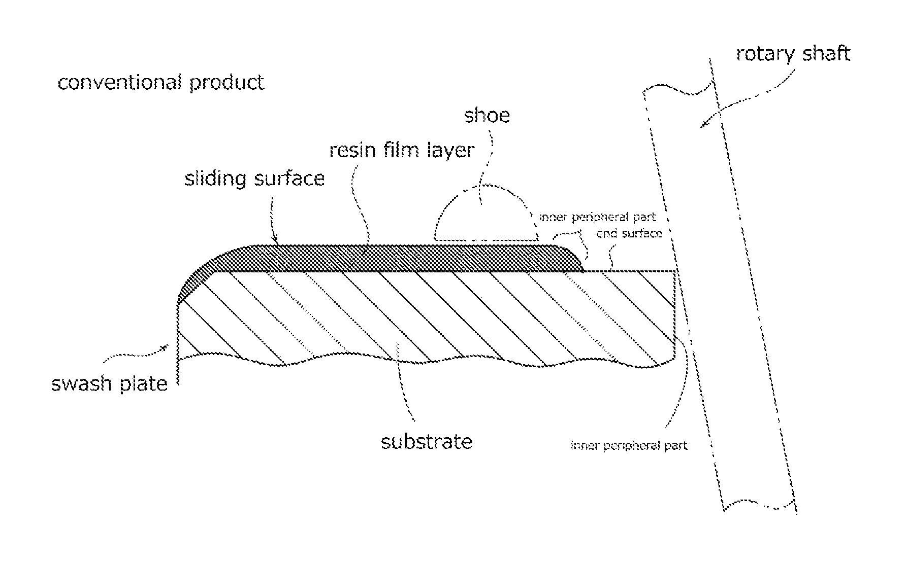
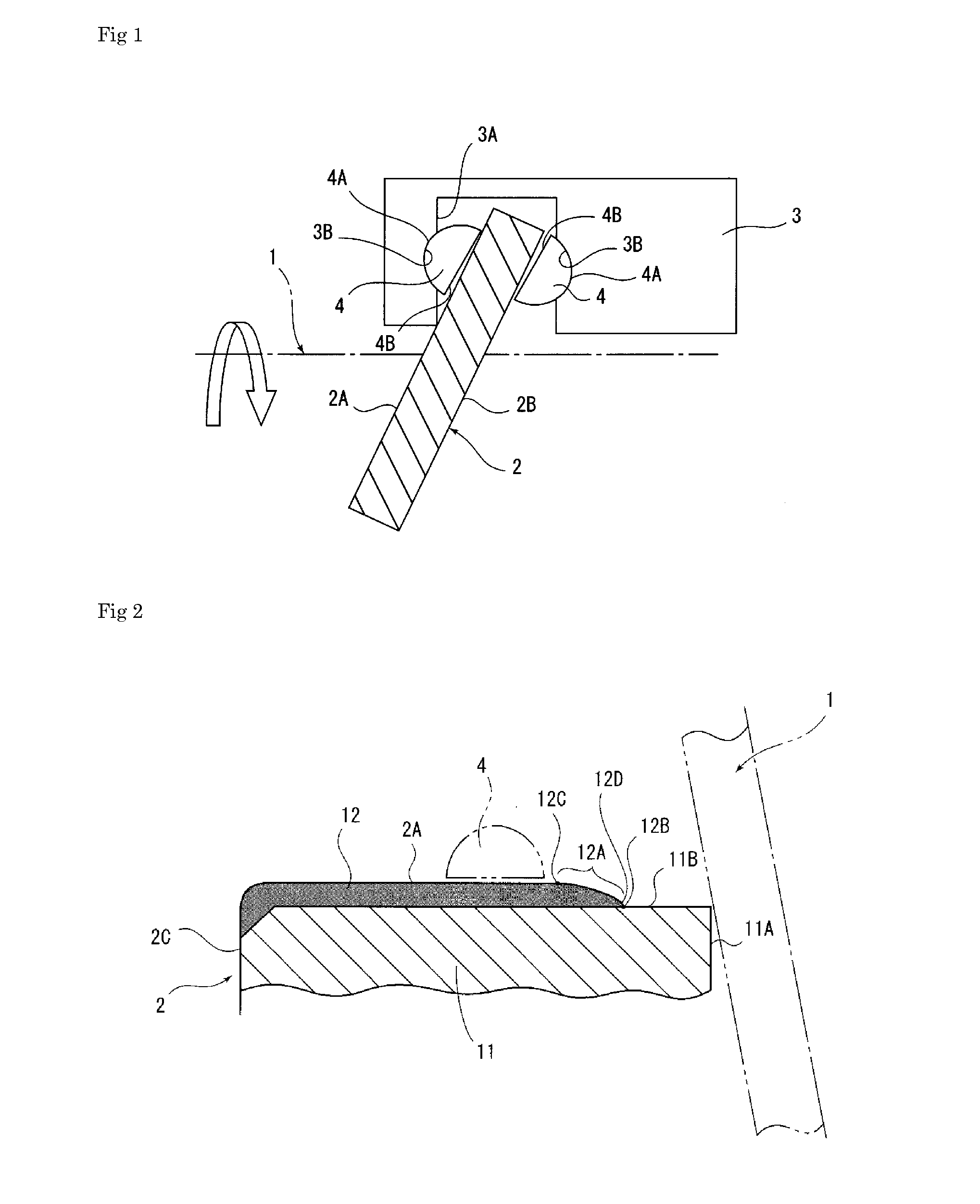
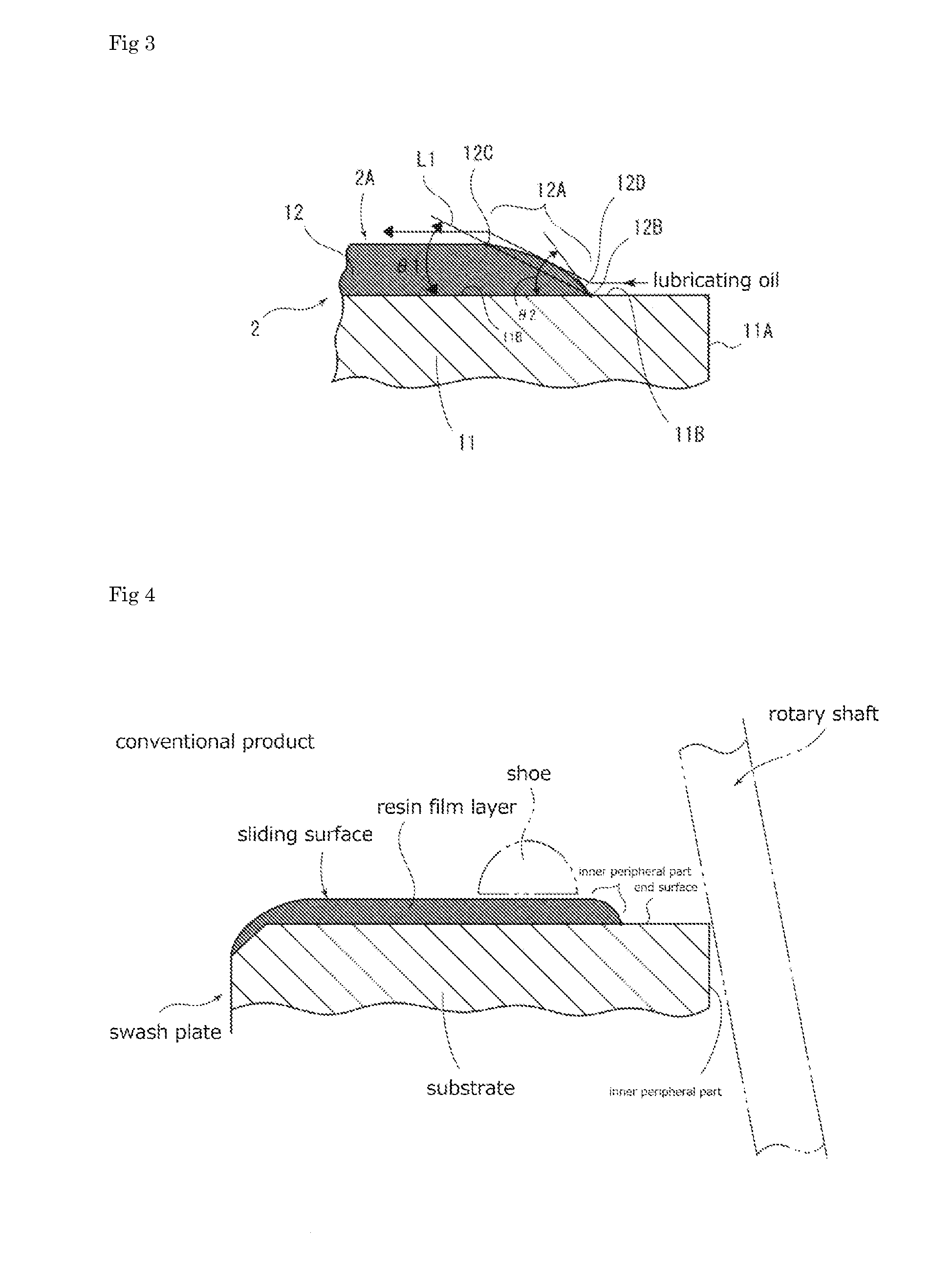
[0020]When explaining the present invention with reference to the illustrated embodiments below, FIG. 1 shows the main parts of a swash plate type compressor. The swash plate type compressor is arranged with a disc-shaped swash plate 2 attached to be tilted to an outer peripheral part of a rotary shaft 1, a plurality of pistons 3 arranged along the rotary shaft 1 and wrap the outer peripheral part of the swash plate 2 by a notch part 3A of one end, and a plurality of hemispherical shoes 4 arranged between a pair of hemispherical recess parts 3B, 3B formed within the notch 3A of each piston 3 and a front surface 2A and rear surface 2B of the swash plate 2. The shoe 4 is arranged with a hemispherical surface 4A which latches to the recess part 3B of the piston 3, and a flat end surface 4B which slides with the front surface 2A or rear surface 2B which are sliding surfaces of the swash plate 2. The shoe 4 is comprised from SUJ2, tempered to the hemispherical surface 4A and end surface ...
PUM
| Property | Measurement | Unit |
|---|---|---|
| Thickness | aaaaa | aaaaa |
| Angle | aaaaa | aaaaa |
| Angle | aaaaa | aaaaa |
Abstract
Description
Claims
Application Information
PatSnap Eureka turns technology decisions into work you can execute. Powered by our Innovation Knowledge Graph, it runs expert workflows across engineering, life sciences, materials and intellectual property. Get your review-ready output in minutes.


