Drive transmission apparatus and image forming apparatus

Inactive Publication Date: 2015-02-05
CANON KK
View PDF4 Cites 10 Cited by
  • Summary
  • Abstract
  • Description
  • Claims
  • Application Information

AI Technical Summary

Benefits of technology

[0016]The present invention has been made in view of the above-mentioned circumstances, and therefore provides a drive transmission apparatus configured to t

Problems solved by technology

Further, when the motive torque greater than necessary is exerted on the output gear 206, the output gear206 unlatched from the solenoid 208 is rotated at high velocity, which leads t

Method used


Image

  • Drive transmission apparatus and image forming apparatus
  • Drive transmission apparatus and image forming apparatus
  • Drive transmission apparatus and image forming apparatus

Examples


first embodiment

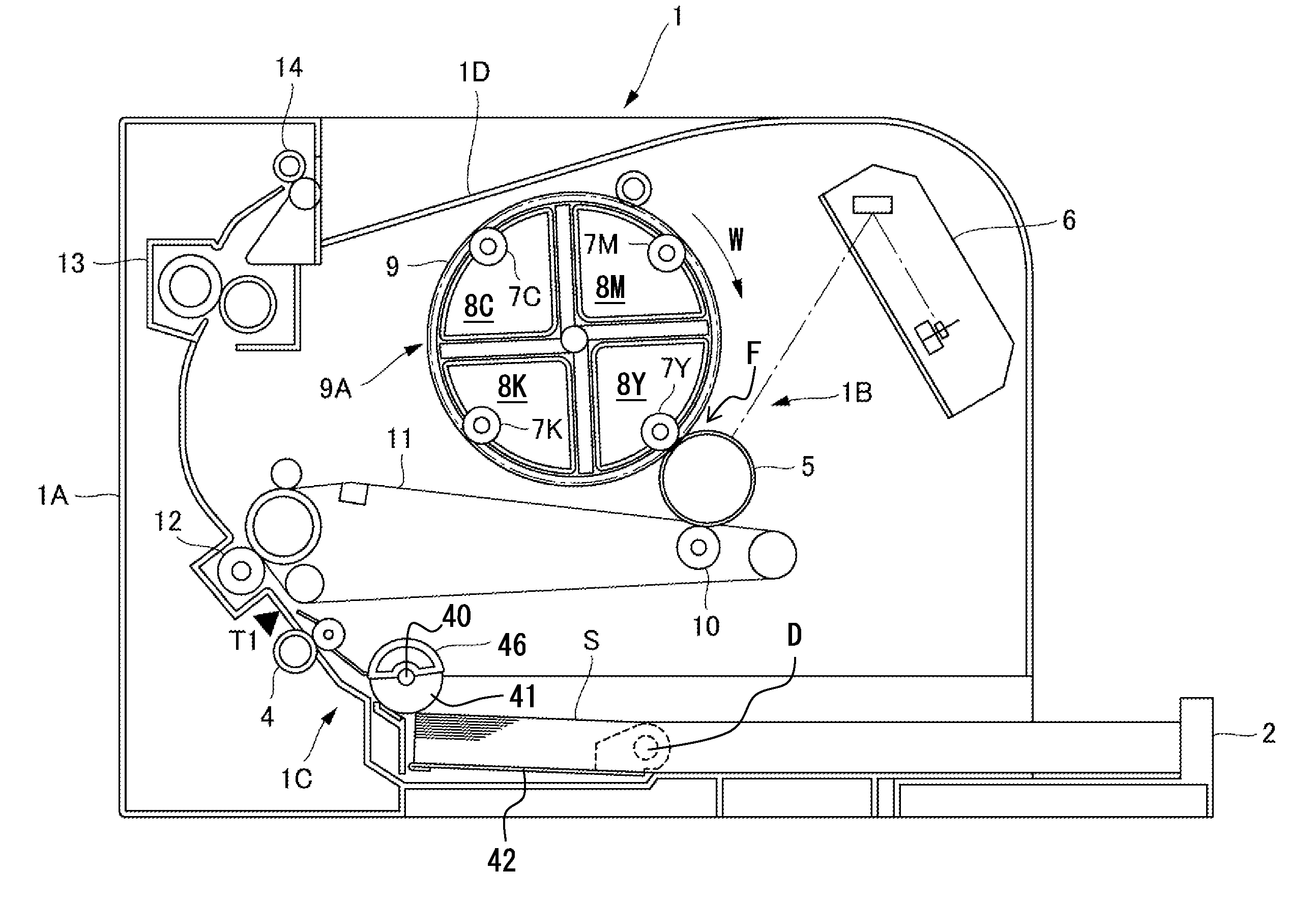
[0041]The embodiments of the present invention will hereinafter be described in detail with reference to the accompanying drawings. FIG. 1 is a view illustrating a structure of a color laser printer 1 as an example of an image forming apparatus according to the present invention. In FIG. 1, the color laser printer 1 includes a color laser printer main body (hereinafter referred to as “printer main body”) 1A as a main body of the image forming apparatus. The printer main body 1A includes an image forming portion 1B and a sheet feed device 1C configured to feed a sheet S to the image forming portion 1B.

[0042]The image forming portion 1B includes a photosensitive drum 5 serving as an image bearing member, a rotary developing device 9A serving as a rotary developing device of the present invention, and a scanner unit 6. Further, the image forming portion 1B includes an endless intermediate transfer belt 11, and a primary transfer roller 10 configured to sequentially transfer, onto the i...

second embodiment

[0070]Next, the present invention will be described. FIG. 11A is an exploded perspective view of a drive transmission apparatus provided in the color laser printer (image forming apparatus) 1 according to the embodiment. FIG. 11B is a front view of an output gear 30 as viewed along the direction indicated by the arrow XIB in FIG. 11A. FIG. 11C is a front view of a preceding gear 31 as viewed along the direction indicated by the arrow XIC in FIG. 11A.

[0071]In FIG. 11A, a drive transmission apparatus 29 includes the output gear 30, the preceding gear 31, and an input gear 34. The output gear 30 includes a partially-toothless small gear portion 30a having a toothless portion, and a partially-toothless large gear portion 30b having a toothless portion. Further, a cam surface 30c is provided on an outer peripheral surface of the output gear 30. Still further, a latch arm 35 is a latch member. The latch arm 35 latches the preceding gear 31 to maintain the preceding gear 31 in a stopped st...


PUM


Abstract

A drive transmission apparatus in which, when immobilization of a preceding gear (21) by a solenoid (22) is canceled, an urging portion urges the preceding gear (21) to rotate in a direction in which the preceding gear (21) meshes with an input gear (24) which rotates at a constant velocity. An interlocking portion causes an output gear (20) to mesh with the input gear (24) in association with the rotation of the preceding gear (21), to rotate the output gear (20) at a low velocity, and to rotate the output gear (20) at a high velocity when the output gear (20) rotates by a predetermined amount.

Description

TECHNICAL FIELD[0001]The present invention relates to a drive transmission apparatus and an image forming apparatus including the drive transmission apparatus.BACKGROUND ART[0002]Conventionally, an image forming apparatus such as a copying machine, a printer, a facsimile machine, and a multifunction peripheral having functions of those apparatus may include a sheet feed device configured to feed a sheet by a feed roller, and a rotary developing device configured to develop an electrostatic latent image formed on a photosensitive drum. As such an image forming apparatus, there is an image forming apparatus in which the feed roller and the rotary developing device are driven by the drive of a drive motor being transmitted to the feed roller and the rotary developing device by a drive transmission apparatus at a predetermined timing.[0003]FIG. 21 is a view illustrating a structure of a rotary developing device which is provided in a conventional electrophotographic color image forming ...

Claims


Application Information

Patent Timeline
IPC IPC(8): F16H1/20F16H55/17
CPCF16H55/17F16H1/20F16H27/08G03G21/1647G03G21/1676B65H3/0607B65H3/0669B65H3/5223B65H2403/421B65H2403/512B65H2403/724B65H2404/1112Y10T74/19614
Inventor KURODA, AKIRAFUKITA, TAKUYAMAZAKI, YOSHIYUKIYAMAGUCHI, NORITOMO
Owner CANON KK
Why Eureka
Try Eureka