Solid state lighting control

a lighting control and solid state technology, applied in the direction of electric variable regulation, process and machine control, instruments, etc., can solve the problems of limiting the (i) flicker of the electronic system, the (ii) of the dimming performance, etc., to improve reliability and/or flicker, reduce the effect of flicker and cost reduction

Inactive Publication Date: 2015-02-05
POWER INTEGRATIONS INC
View PDF5 Cites 57 Cited by
  • Summary
  • Abstract
  • Description
  • Claims
  • Application Information

AI Technical Summary

Benefits of technology

[0028]There may further be provided the dimmer interface circuit, configured to deliver a first average current followed a second lower average current to the charge store to thereby deliver the amount of charge. The higher first current may allow to maintain the triac on, e.g., to latch and / or hold the triac. Such a current profile may allow more reliable triac latch and / or hold and thus for example reduce flicker.
[0029]There may further be provided the dimmer interface circuit, configured to control a peak voltage of the converter output voltage to thereby perform said converter output voltage control. Controlling the value of this peak voltage, for example using a digital or analogue peak detector, may serve to ensure that the desired target voltage difference is achieved at the following brightness control voltage transition. Thus improvements in reliability and / or flicker may be achieved.
[0030]There may further be provided the dimmer interface circuit, wherein the charge store comprises a non-electrolytic capacitor. This may allow, e.g., cost reduction.

Problems solved by technology

However, while their energy efficiency is widely-touted, current LED lamps suffer from a number of disadvantages in which the driver electronics may play a part:poor light quality—while LED selection and optical design are very relevant in this regard, the driver electronics impose limitations on (i) visible flicker, (ii) invisible flicker, and / or (iii) dimming performance.
In general, light quality is frequently considered to be inferior to that of incandescent bulbs, in particular when using typical AC dimmer controls;high cost—a good quality replacement LED lamp costs in the region of £20, a clear disincentive to consumers.
Although the LED chip and optical and mechanical parts form the major part of the bill of materials, the electronics are presently too expensive;disappointing lifetime—the main argument used in justifying the high asking price of LED lamps is that they last many times as long as incandescent lamps.
This originates in the long lifetimes of LED chips themselves, however some of the driver electronics parts tend to have shorter lifetimes than the LEDs.
Many of these same disadvantages have been previously encountered in the development of fluorescent lamps, in particular that of dimmable compact fluorescent lamps (CFLs).
In this regard, the following phenomena are of note when LED lamps are combined with phase modulating dimmers: visible pulsing of LEDs, audible noise from LED light bulbs, LEDs never fully turn on, LEDs turn on when the dimmer is turned off, and / or substantial inrush current when a triac turns on, potentially damaging both the triac and LED drivers.

Method used


Image

  • Solid state lighting control
  • Solid state lighting control
  • Solid state lighting control

Examples


Embodiment Construction

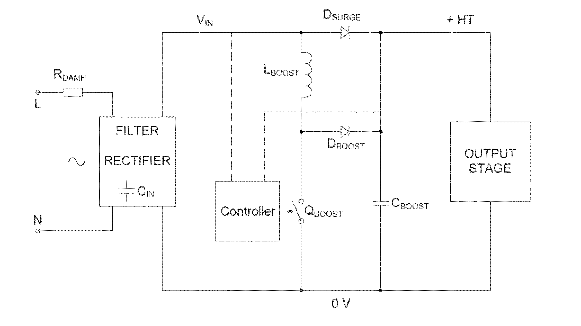
[0053]Generally, an embodiment provides a dimmer interface for an LED driver. A preferred embodiment provides advantages relating to LED lamp performance when used with AC dimmers. Advantages of an embodiment may for example relate to quality of light from an LED lamp—particularly when controlled by AC dimmers—and / or high electronic parts cost.

[0054]An embodiment provides control of boost output voltage to be below the instantaneous mains input voltage when the dimmer triac fires, by a target voltage difference. This may for example be achieved by controlling boost converter switching (for example by employing current shaping for optimal triac latch / hold), and / or by controlling output stage switching / power consumption. Additionally or alternatively, an embodiment provides an LED driver controller in a preferably 8-pin package, which senses VIN at a pin connected to a boost converter switch control terminal and senses +HT at a pin sensing input voltage of the output stage.

[0055]Embod...


PUM


Abstract

This invention generally relates to solid state lighting control, and more particularly to a dimmer interface circuit and a method for reducing ringing on a drive signal to a solid state lighting device. An embodiment is a dimmer interface circuit for controlling brightness of a solid state light emission device, the interface circuit having an input to receive a brightness control voltage from a dimmer circuit and comprising: a voltage converter to provide a converter output voltage and having an inductive component and a charge store, the charge store controllably coupled to receive charge from the inductive component to thereby convert the brightness control voltage to the converter output voltage; and control circuitry comprising: an input to receive a voltage level indication of the brightness control voltage; an input to receive a voltage level indication of the converter output voltage; a comparison circuit to compare a said received brightness control voltage level indication and a said received converter output voltage level indication; and a transition detector to detect a transition of the brightness control voltage, said transition for turning a said solid state light emission device on, wherein the control circuitry is configured to control the voltage converter dependent on a said comparison of said level indications received at a time of a said transition in a first cycle of the brightness control voltage, such that a difference between the brightness control voltage and the converter output voltage at a time of a said transition in a second, later said cycle is closer to a target voltage difference or target voltage difference range than a said difference at the time of the transition in the first cycle.

Description

RELATED APPLICATIONS[0001]This application claims priority under 35 U.S.C. 119(e) to U.S. Provisional Application No. 61 / 861,047, filed Aug. 1, 2013; which application is incorporated herein by reference in its entirety.FIELD OF THE INVENTION[0002]This invention generally relates to solid state lighting control, and more particularly to a dimmer interface circuit, solid state lighting device drivers and a method for reducing ringing on a drive signal to a solid state lighting device.BACKGROUND TO THE INVENTION[0003]There is high demand for good quality LED lamps to replace incandescent light bulbs. However, while their energy efficiency is widely-touted, current LED lamps suffer from a number of disadvantages in which the driver electronics may play a part:[0004]poor light quality—while LED selection and optical design are very relevant in this regard, the driver electronics impose limitations on (i) visible flicker, (ii) invisible flicker, and / or (iii) dimming performance. In gener...

Claims


Application Information

Patent Timeline
Patent Type & Authority Applications(United States)
IPC IPC(8): H05B33/08H05B44/00
CPCH05B33/0815H05B33/0851Y10S362/80H05B45/10H05B47/17H05B45/38H05B45/385H05B45/375H02M3/156Y02B20/30
Inventor WERNER, ANTONIUS JACOBUS JOHANNES
Owner POWER INTEGRATIONS INC
Why Eureka
Try Eureka