Low-ripple power supply

Inactive Publication Date: 2015-02-05
ALGOLTEK
View PDF2 Cites 1 Cited by
  • Summary
  • Abstract
  • Description
  • Claims
  • Application Information

AI Technical Summary

Benefits of technology

[0010](1) utilize present electronic circuit devices to avoid ex

Problems solved by technology

However, present power supplies commonly encounter issues of considerable ripples during usage regardless of their type, which result in the instability of the op

Method used


Image

  • Low-ripple power supply
  • Low-ripple power supply
  • Low-ripple power supply

Examples


Example

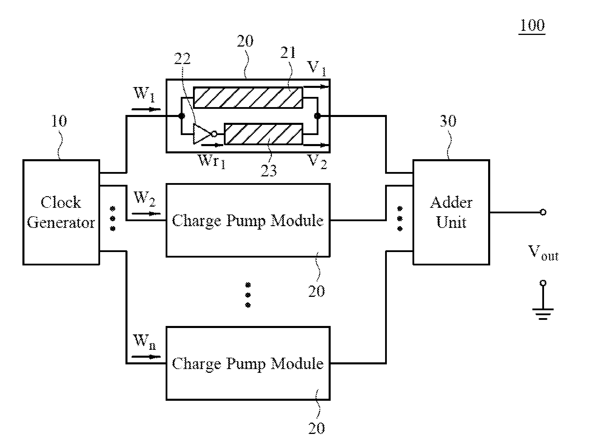
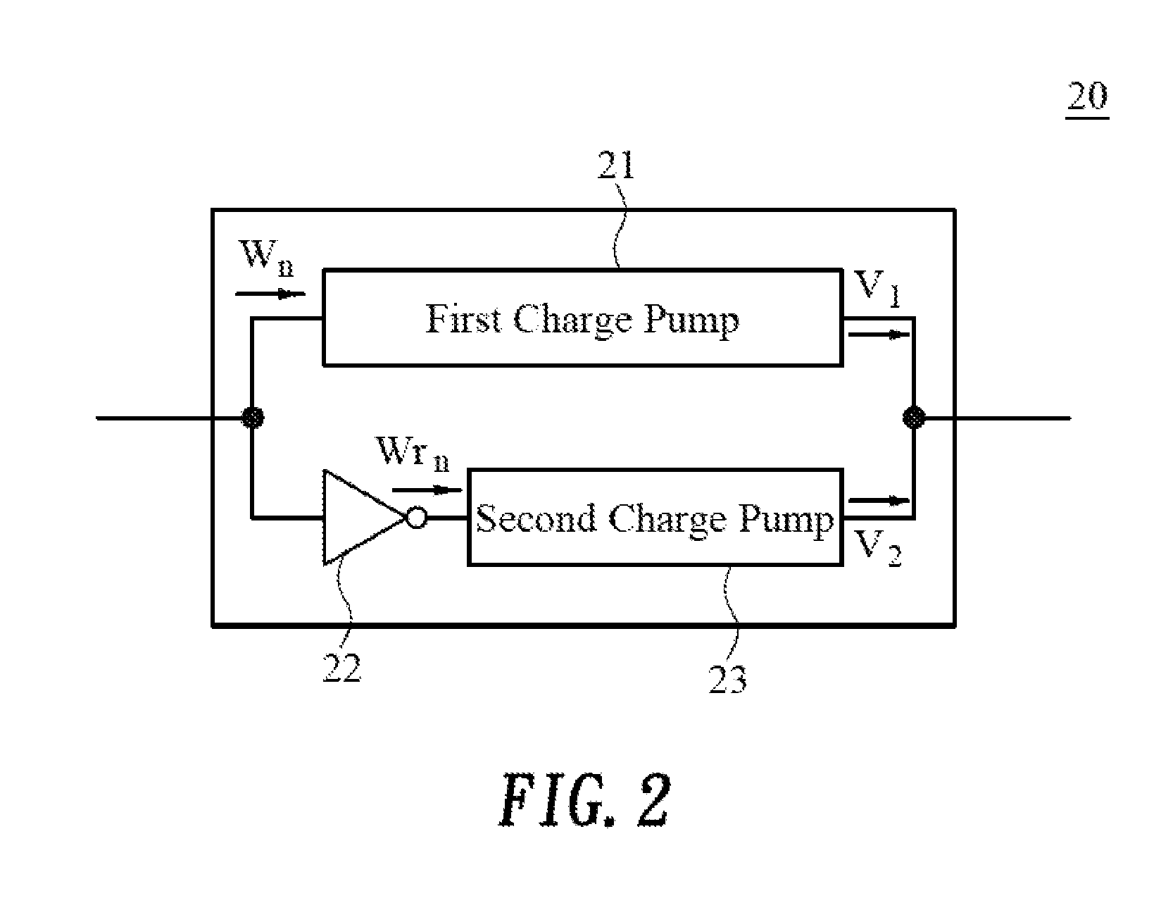
[0016]FIG. 1 shows an embodiment of the low-ripple power supply 100 comprising a clock generator 10, a plurality of charge pump modules 20, and an adder unit 30, wherein each of the plurality of charge pump modules 20 comprises a first charge pump 21, an inverter 22, and a second charge pump 23.

[0017]As shown in FIG. 1, the clock generator 10 outputs a plurality of clock signals (W1˜Wn), wherein each of the plurality of clock signals has a different phase. The clock generator may be a ring oscillator circuit (ROSC), and each of the plurality of clock signals may be outputted from each oscillator circuit stage of the ring oscillator circuit, wherein the number of clock signals is the same as the number of oscillator circuit stages of the ring oscillator circuit.

[0018]As shown in FIG. 1 and FIG. 2, the plurality of charge pump modules 20 are electrically connected with the clock generator 10 and each of the plurality of charge pump modules 20 is inputted with a corresponding clock sig...


PUM


Abstract

The present invention is a low-ripple power supply comprising a clock generator, a plurality of charge pump modules, and an adder unit. The low-ripple power supply inputs each of a plurality of clock signals generated by the clock generator into each of the plurality of charge pump modules. Since each of the plurality of charge pump modules sends the inputted corresponding clock signal into two paths to be inputted into the first and the second charge pump, respectively, and the corresponding clock signal inputted into the second charge pump undergoes an inversion by the inverter, by adding the first voltage outputted by the first charge pump and the second voltage outputted by the second charge pump, the ripples may be eliminated; finally, the adder unit adds the voltages outputted by each of the plurality of charge pump modules to yield a low-ripple DC voltage.

Description

BACKGROUND OF THE INVENTION[0001]1. Technical Field[0002]The invention relates to a low-ripple power supply, and more particularly, to a low-ripple power supply manufactured using present electronic circuit devices entirely, having low cost and feasibility of mass production, and comprising a plurality of charge pump modules.[0003]2. Description of Related Art[0004]Power supplies are mandatory devices for all electronic products, and the main function is to convert the voltage inputted to the power supply into direct current (DC) voltage to be supplied to connected electronic products. Power supplies come in many varieties, which mainly include switching-mode power supplies, transformers, rectifiers, etc.[0005]However, present power supplies commonly encounter issues of considerable ripples during usage regardless of their type, which result in the instability of the operation of electronic products. Moreover, the electronic product may occasionally blow the fuse or be damaged due t...

Claims


Application Information

Patent Timeline
IPC IPC(8): G06G7/10
CPCG06G7/10H02M1/14H02M3/07H02M3/077H02M3/1586
Inventor ZHANG, DALEECHAN, SHENG-CHIEHLEE, TZUEN-HWAN
Owner ALGOLTEK
Why Eureka
Try Eureka