Illumination device, projection type image display device, and optical device

a technology of projection type and image display, which is applied in the direction of projection device, television system, instrument, etc., can solve the problems of unfavorable use of mercury-based high-intensity discharge lamps, unfavorable use of mercury-based high-pressure mercury lamps, and short life of lamps, so as to effectively suppress the speckle generated on the screen

Active Publication Date: 2015-02-05
DAI NIPPON PRINTING CO LTD
View PDF6 Cites 10 Cited by
  • Summary
  • Abstract
  • Description
  • Claims
  • Application Information

AI Technical Summary

Benefits of technology

[0020]According to the illumination device of the present invention, the optical scanning section scans the coherent light to cause the illumination light to be emitted from the optical path conversion system to illuminate the area to be illuminated at an angle changing with time. This allows the speckle gene

Problems solved by technology

However, a high-intensity discharge lamp such as the high-pressure mercury lamp has a comparatively short life, so that when the high-intensity discharge lamp is used for a projector, the lamp needs to be replaced frequently with new one.
Moreover, the use of the high-intensity discharge lamp disadvantageously increases a size of the projector.
Moreover, it is unfavorable to use the high

Method used


Image

  • Illumination device, projection type image display device, and optical device
  • Illumination device, projection type image display device, and optical device
  • Illumination device, projection type image display device, and optical device

Examples


Embodiment Construction

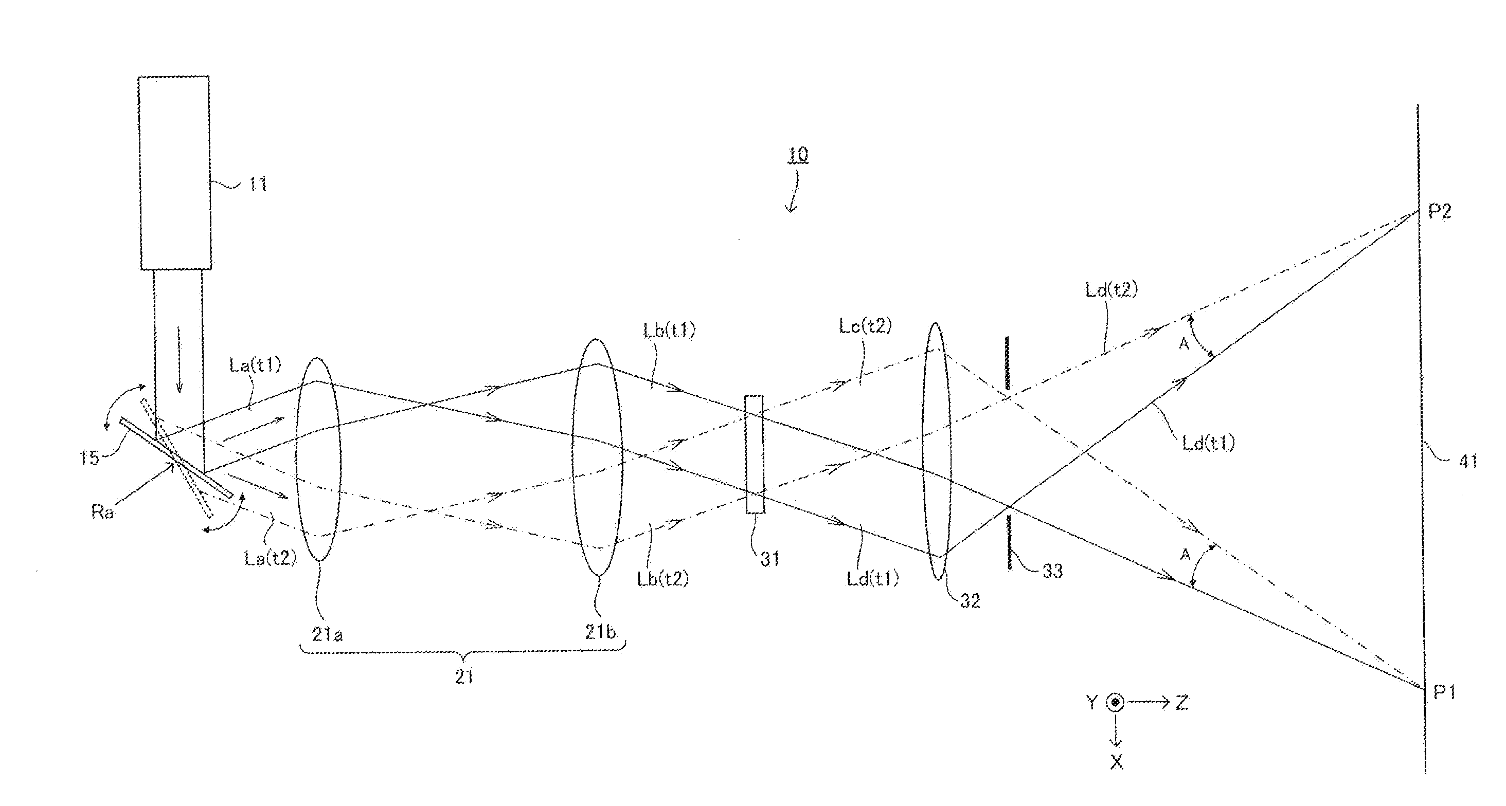
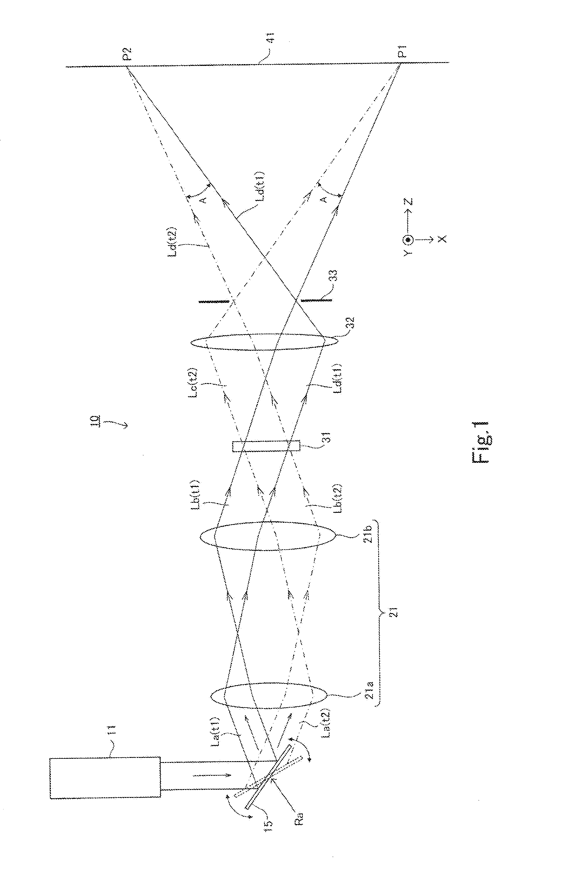
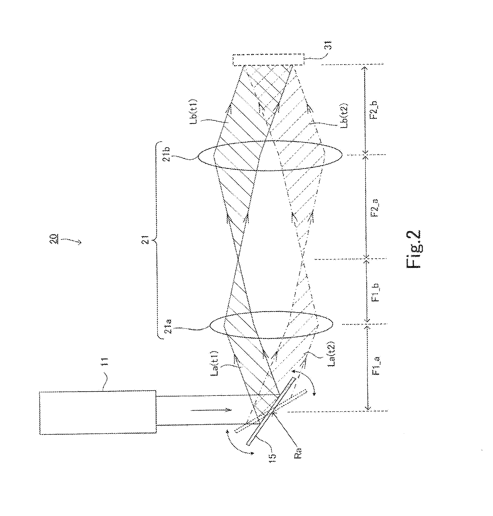
[0026]Now, an illumination device and a projection type image display device according to an embodiment of the present invention will be described with reference to the drawings. FIG. 1 is a view illustrating a configuration of a projection type image display device provided with an illumination device according to an embodiment of the present invention. It should be noted that drawings described hereinafter are each a schematic diagram, and may represent different shape, dimension, and position from those actually illustrated.

[0027]A projection type image display device 10 according to the present embodiment includes an illumination device 20, an optical modulation element 31 for forming an image, and a projection optical system 32 that projects an image formed by the optical modulation element 31 on a screen 41. In the drawings, a surface of the screen 41 on which an image is projected is assumed to be X-Y plane, and an axis normal to the X-Y plane is assumed to be a Z-axis. As th...


PUM


Abstract

To provide an illumination device and a projection type image display device that illuminate an area to be illuminated (image formation area) under conditions where speckle noise is less noticeable.
An illumination device according to the present invention includes: a light source 11 that emits coherent light; an optical scanning section 15 that scans the coherent light emitted from the light source 11; and an optical path conversion system 21 configured to allow the coherent light scanned by the optical scanning section 15 to illuminate an area to be illuminated sequentially in an overlapping manner. An incident angle of the coherent light that enters respective points of the area to be illuminated changes with time.

Description

TECHNICAL FIELD[0001]The present invention relates to an illumination device that uses coherent light such as laser light, a projection type image display device that uses the coherent light to illuminate an optical modulation element to project an image on a screen, and an optical device for use in the illumination device and projection type image display device.BACKGROUND ART[0002]There is known a projector (projection type image display device) that uses an optical modulation element (micro display) such as a liquid crystal or MEMS to visualize illumination light from a light source and projects an image based on the illumination light on a screen. Some of such projectors use, as its light source, a white light source such as a high-pressure mercury lamp and projects an image on a screen while magnifying an image obtained by illuminating a two-dimensional optical modulation element such as a liquid crystal by means of projection optical system.[0003]However, a high-intensity disc...

Claims


Application Information

Patent Timeline
IPC IPC(8): G02B27/48G02B26/10G02B26/12H04N9/31
CPCG02B27/48H04N9/3129G02B26/105H04N9/3161G02B26/106H04N9/3155G02B26/12G02B26/0808G02B26/0816G02B26/101G02B26/125G03B21/2033G03B21/2066G03B21/208G02B26/10H04N5/74H04N9/14
Inventor TANIGUCHI, YUKIOKURASHIGE, MAKIOOOYAGI, YASUYUKI
Owner DAI NIPPON PRINTING CO LTD
Why Eureka
Try Eureka