Fuel cell

Inactive Publication Date: 2015-02-05
NISSAN MOTOR CO LTD
9 Cites 2 Cited by

AI-Extracted Technical Summary

Problems solved by technology

However, the region (non-contact surface) which is not supported by the ribs has low surface pressure (uneve...

Benefits of technology

[0006]However, the enlarged contact surface width causes a problem of decreasing the size of the non-co...

Abstract

Disclosed is a fuel cell including a support which is made of a metal porous base material and disposed between a membrane electrode assembly and at least either of first ribs and second ribs. Contact surfaces of the first ribs and contact surfaces of the second ribs with the membrane electrode assembly or the support are offset from each other in a cross sectional view in the direction orthogonal to a gas passage direction.

Application Domain

Electrolyte holding meansSolid electrolytes +3

Technology Topic

Image

  • Fuel cell
  • Fuel cell
  • Fuel cell

Examples

  • Experimental program(5)

Example

First Embodiment
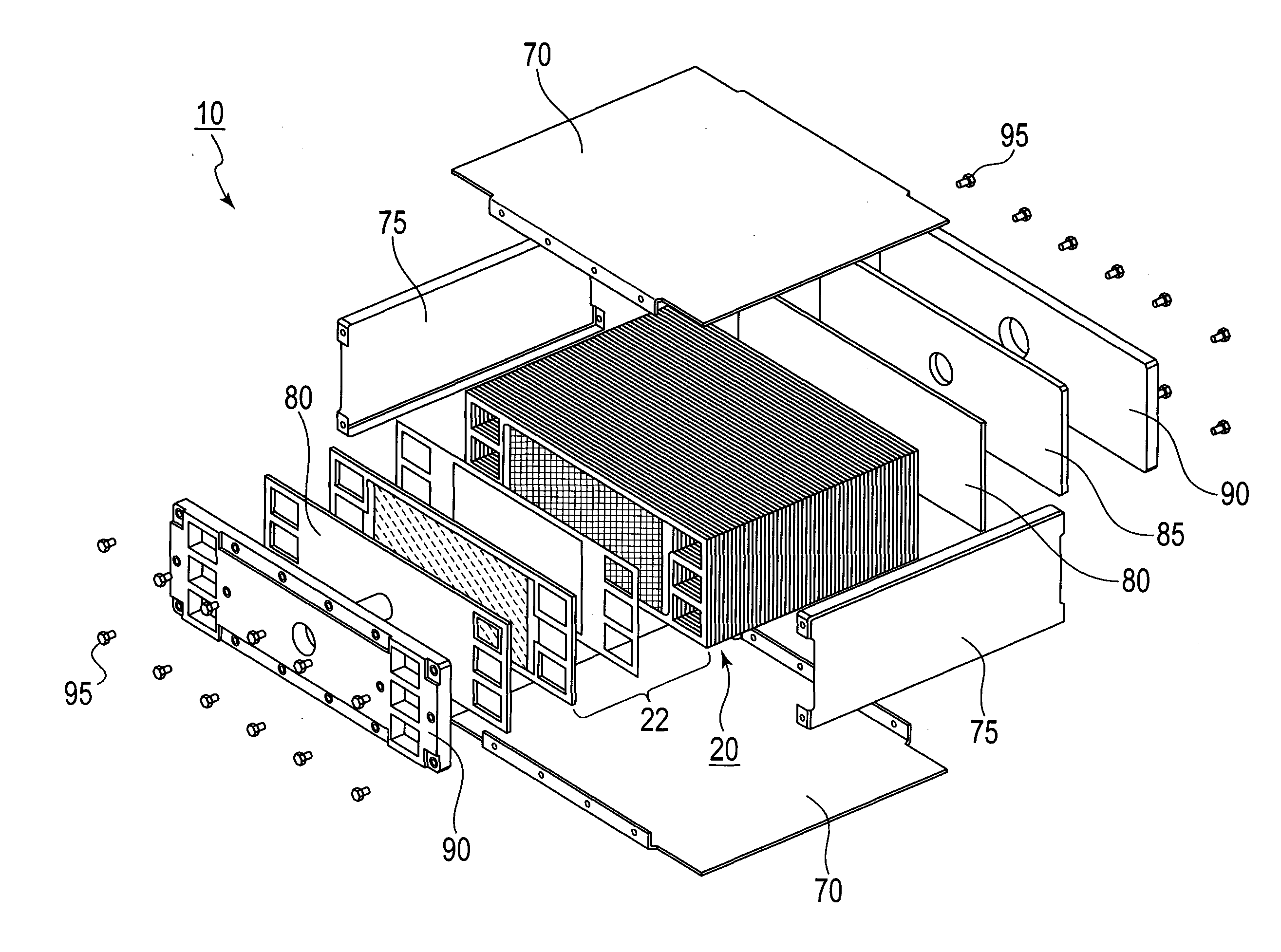
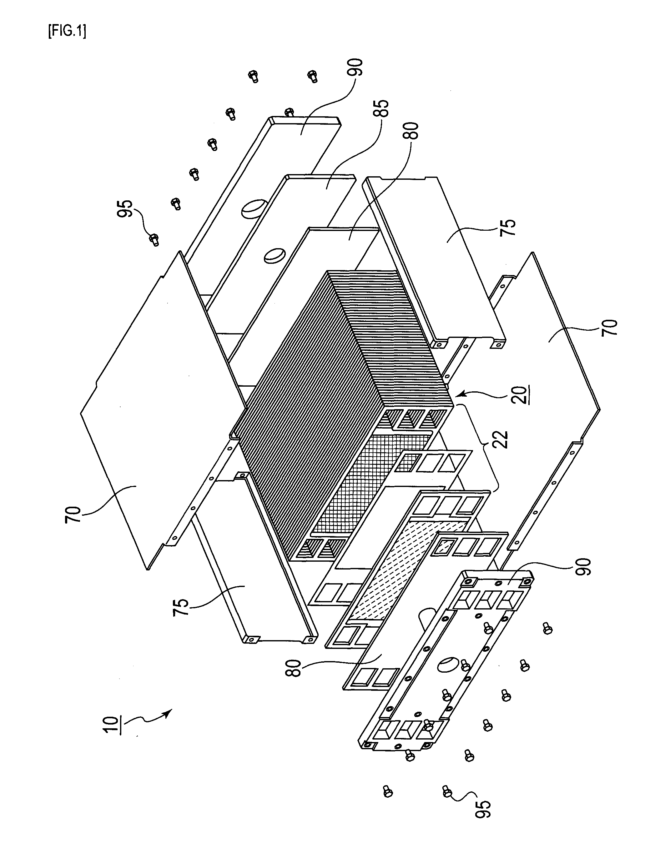
[0031]FIG. 1 is an exploded perspective view for describing a fuel cell according to a first embodiment.
[0032]A fuel cell 10 according to the first embodiment is easily downsized and has good gas diffusion properties, and enables its surface pressure to be evenly distributed. For example, it is formed from a polymer electrolyte fuel cell using hydrogen as fuel, and is utilized as a power supply. For the polymer electrolyte fuel cell (PEFC), downsizing, densification, and an increased power are possible. It is preferably applied as a power supply for driving mobile objects such as a vehicle having a limited mount space, particularly preferably applied to automobiles in which the system frequently starts and stops, or the output frequently changes. In this case, the PEFC can be mounted under the seats at the center of the car body, in the lower part of the rear trunk room, and in the engine room in the vehicle front portion in automobiles (fuel-cell vehicles), for example. It is preferably mounted under the seats from a viewpoint that a large interior space and trunk room are secured in the car.
[0033]As shown in FIG. 1, the fuel cell 10 has a stack part 20, fastener plates 70, reinforcing plates 75, current collectors 80, a spacer 85, end plates 90, and bolts 95.
[0034]The stack part 20 includes a stack body of single cells 22. The single cell 22 has a membrane electrode assembly, separators, ribs, and supports, as describe below.
[0035]The fastener plates 70 are disposed on a bottom surface and an upper surface of the stack part 20, and the reinforcing plates 75 are disposed on both sides of the stack part 20. That is to say, the fastener plates 70 and the reinforcing plates 75 jointly constitute a casing surrounding the stack part 20.
[0036]The current collectors 80 are formed from conductive members with gas impermeability, such as a dense carbon and a copper plate. They are provided with an output terminal for outputting an electromotive force generated in the stack part 20, and disposed at both ends of the stack of the single cells 22 in the stacking direction (at the front and the back of the stack part 20).
[0037]The spacer 85 is disposed outside of the current collector 80 disposed at the back of the stack part 20.
[0038]The end plates 90 are formed of a material with rigidity, for example, a metallic material such as steel, and disposed outside the current collector 80 disposed at the front of the stack part 20 and outside the spacer 85. The end plates 90 have a fuel gas inlet, a fuel gas outlet, an oxidant gas inlet, an oxidant gas outlet, a cooling water inlet, and a cooling water outlet in order to supply or discharge fuel gas (hydrogen), oxidant gas (oxygen), and a coolant (cooling water) to circulate through the stack part 20.
[0039]The bolts 95 are used to keep the internally located stack part 20 in a pressed state by: fastening the end plates 90, the fastener plates 70, and the reinforcing plates 75 together; and making a fastening force exerted in the stacking direction of the single cells 22. The number of bolts 95 and the positions of bolt holes can be appropriately changed. In addition, the fastening mechanism is not limited to threaded fasteners, and other means are also applicable.
[0040]FIG. 2 is a cross-sectional view for describing a cell structure according to the first embodiment, and FIG. 3 is a plan view for describing the supports shown in FIG. 2.
[0041]Each single cell 22 has a membrane electrode assembly 30, separators 40 and 45, multiple ribs 50 and 55, and supports 60 and 65.
[0042]The membrane electrode assembly 30 has a polymer electrolyte membrane 32 and catalyst layers 34 and 36, as shown in FIG. 2.
[0043]The catalyst layer 34 includes a catalytic component, a conductive catalyst carrier for carrying the catalytic component, and a polymer electrolyte. The catalyst layer 34 is an anode catalyst layer in which the hydrogen oxidation reaction proceeds, and is disposed on one side of the polymer electrolyte membrane 32. The catalyst layer 36 includes a catalytic component, a conductive catalyst carrier for carrying the catalytic component, and a polymer electrolyte. The catalyst layer 36 is a cathode catalyst layer in which the oxygen reduction reaction proceeds, and is disposed on the other side of the polymer electrolyte membrane 32.
[0044]The polymer electrolyte membrane 32 has a function to allow protons generated in the catalyst layer (anode catalyst layer) 34 to selectively permeate into the catalyst layer (cathode catalyst layer) 36, and a function as a partition to prevent mixture of the fuel gas supplied to the anode side and the oxidant gas supplied to the cathode side.
[0045]The separators 40 and 45 have a function to electrically connect the single cells in series and a function as a partition to separate the fuel gas, the oxidant gas, and the coolant from each other. The separators 40 and 45 have substantially the same shape as the membrane electrode assembly 30 and are formed by pressing a stainless steel plate. The stainless steel plate is preferable in terms of ease of complex machining and good conductivity, and it can be also subjected to corrosion-resistant coating if necessary.
[0046]The separator 40 is an anode separator disposed on the anode side of the membrane electrode assembly 30, and is facing opposite to the catalyst layer 34. The separator 45 is a cathode separator disposed on the cathode side of the membrane electrode assembly 30, and is facing opposite to the catalyst layer 36. The separators 40 and 45 have multiple manifolds for circulating the fuel gas, the oxidant gas, and the coolant. The manifolds respectively communicate with the fuel gas inlet, the fuel gas outlet, the oxidant gas inlet, the oxidant gas outlet, the cooling water inlet, and the cooling water outlet provided in the end plates 90.
[0047]The ribs 50 and 55 formed from protrusions having a rectangular cross-section, which are parts of separators 40 and 45. To put it specifically, the ribs 50 and 55 and the separators 40 and 45 are simultaneously formed (integrally formed) by pressing the stainless steel plates. The ribs 50 are first ribs disposed in parallel with each other and extending in an extending direction (gas passage direction) of the gas passage space 42 defined between the membrane electrode assembly 30 and the separator 40 in the extending direction. The gas passage space 42 is utilized to supply the fuel gas to the catalyst layer 34. The ribs 55 are second ribs disposed in parallel with each other and extending in the extending direction (gas passage direction) of the gas passage space 47 defined between the membrane electrode assembly 30 and the separator 45 in the extending direction (gas passage direction). The gas passage space 47 is utilized to supply the oxidant gas to the catalyst layer 36.
[0048]The supports 60 and 65 are conductive plate-shaped members which have bending rigidity and bending strength larger than those of the membrane electrode assembly 30, and are made of porous base materials to supply gases to the catalyst layers.
[0049]The supports 60 and 65 are made of metal nets (metal meshes), as shown in FIG. 3. The support 60 is disposed between the catalyst layer 34 and the ribs 50. The support 65 is disposed between the catalyst layer 36 and the ribs 55.
[0050]Contact surfaces 52 of the ribs 50 and contact surfaces 57 of the ribs 55 are offset from each other in a cross sectional view in the direction orthogonal to the gas passage direction. Contact surfaces 52 of the ribs 50 and contact surfaces 57 of the ribs 55 are positioned at predetermined intervals in the direction orthogonal to the gas passage direction and the stacking direction of the single cells 22 (so as not to overlap with each other in a projection in the stacking direction), with the support 60, the membrane electrode assembly 30 and the support 65 interposed in between. Contact surfaces 52 and 57 are alternately arranged in the direction orthogonal to the gas passage direction and the stacking direction. This arrangement provides a bending moment to the support 60, the membrane electrode assembly 30 and the support 65, so that: compressive force acts near the contact surfaces (load points) 52 and 57; surface pressure is evenly distributed over the entire surface of a power-generating area, as compared to the case where the contact surfaces 52 and the contact surfaces 57 overlap each other (where the contact surfaces 52 are arranged to be opposite to the contact surfaces 57, respectively). Because the rigidity and the strength are increased by the presence of the supports 60 and 65, damage of the membrane electrode assembly 30 due to the generation of the bending moment is suppressed. In addition, because the widths W11 and W21 of the contact surfaces 52 and 57 need not to be enlarged, it is possible to avoid a problem of reduced gas diffusion properties through the regions (non-contact surfaces) which are supported by none of the ribs 50 and 55. Further, because the surface pressure is not evenly distributed by only the support 60 or the support 65 (only the rigidity thereof), thicknesses T1 and T2 of the supports 60 and 65 can be made thinner. In short, a fuel cell which is easily downsized and has good gas diffusion properties, and enables the surface pressure to be evenly distributed can be provided. In this case, the ribs 50 and 55 have a rectangular cross-section, and thus the widths W11 and W21 (contact surface widths) of the contact surfaces 52 and 57 of the ribs 50 and 55 coincide with the widths (widths of top surfaces) of the ribs 50 and 55, respectively. Further, non-contact surface widths W12 and W22 are defined by the distance between the contact surfaces 52 and 57.
[0051]The supports 60 and 65 have bending rigidity larger than that of the membrane electrode assembly 30 and the bending rigidity as a whole is improved so that: the compressive forces exerted from the contact surfaces 52 and 57 are also transmitted to the regions around the areas in contact with the contact surfaces 52 and 57; and the surface pressure in the power-generating area is more evenly distributed. The supports 60 and 65 (metal porous base materials) are present on both sides of the membrane electrode assembly 30, and thus electrical conductivity in the in-plane direction inside the single cell is improved. Tenting (passage blockage) can be prevented whichever side of the membrane electrode assembly gas differential pressure is applied to.
[0052]The supports 60 and 65 are made of metal so that: the strength of the supports 60 and 65 is easily improved; and rib pitches (distance between the centers of each two adjacent ribs) P1 and P2 of the ribs 50 and 55 can be increased while the strength to withstand a stacking load is maintained.
[0053]The thickness T1 of the support 60 is preferably the same as the thickness T2 of the support 65. In this case, the membrane electrode assembly 30 may be located near a bending neutral surface, and thus the bending stress to the membrane electrode assembly 30 is eased.
[0054]The rib pitches P1 and P2 are preferably the same. In this case, the amount of relative shift S representing a distance between the contact surfaces 52 of the ribs 50 and the contact surfaces 57 of the ribs 55 is easily set at the maximum. For example, the bending moment is maximized by shifting the contact surfaces 52 of the ribs 50 and the contact surfaces 57 of the ribs 55 from each other by the distance corresponding to simply a half of the rib pitch, and the surface pressure unevenness can be reduced by uniformly disposing bending-moment-generating parts.
[0055]The rib pitches P1 and P2 are preferably equal to or less than the value calculated from the formula (2×(the length of the supports 60 and 65 in the gas passage width direction)×(the thickness of the supports 60 and 65)2×(the bending strength of the supports 60 and 65))/(the stacking load for each of the ribs 50 and 55). In this case, passage occupancy (area occupancy of the gas passage space) increases and therefore the gas diffusion properties can be improved.
[0056]The ribs 50 and 55 are preferably disposed such that the amount of relative shift S representing a distance between the contact surfaces 52 of the ribs 50 and contact surfaces 57 of the ribs 55 is the maximum. In this case, the bending moment is maximized and the bending-moment-generating parts are uniformly disposed, thereby reducing surface pressure unevenness.
[0057]The supports 60 and 65 are in direct contact with the catalyst layers 34 and 36, and the ribs 50 and 55 are integrated with the separators 40 and 45 so that the electric conduction between the catalyst layers 34 and 36 and the separators 40 and 45 is sufficiently secured to keep the electrical resistance of the single cell low. Therefore, the sufficient gas diffusion properties and the sufficient electrical conductivity are secured, and thus the omission of a gas diffusion layer (GDL) such as a carbon paper achieves a thinner fuel cell. It should be noted that the supports 60 and 65 can also include a gas diffusion layer if necessary.
[0058]Next, the materials, the size, and others of each component member will be described in detail.
[0059]For the polymer electrolyte membrane 32, a fluorine polymer electrolyte membrane made of perfluorocarbon sulfonic acid polymer, a hydrocarbon resin film having a sulfonic acid group, and a porous membrane impregnated with an electrolyte component such as phosphoric acid and ionic liquid can be applied. Examples of the perfluorocarbon sulfonic acid polymer include Nafion (registered trademark, produced by E. I. du Pont de Nemours and Company), Aciplex (registered trademark, produced by Asahi Kasei Corporation), and Flemion (registered trademark, produced by ASAHI GLASS CO., LTD.). The porous membrane is formed of polytetrafluoroethylene (PTFE) and polyvinylidene fluoride (PVDF).
[0060]Although the thickness of the polymer electrolyte membrane 32 is not particularly limited, the thickness is preferably 5 to 300 μm, more preferably 10 to 200 μm in view of the strength, the durability, and the output characteristics.
[0061]The catalytic component used in the catalyst layer (cathode catalyst layer) 36 is not particularly limited as long as having catalysis for the oxygen reduction reaction. The catalytic component used in the catalyst layer (anode catalyst layer) 34 is not particularly limited as long as having catalysis for the hydrogen oxidation reaction.
[0062]The catalytic component is specifically selected from, for example, metals such as platinum, ruthenium, iridium, rhodium, palladium, osmium, tungsten, lead, iron, chromium, cobalt, nickel, manganese, vanadium, molybdenum, gallium, and aluminum, their alloys, and others. The catalytic component preferably includes at least platinum in order to improve the catalytic activity, the poisoning resistance to carbon monoxide, the thermal resistance, and others. The catalytic component applied to the cathode catalyst layer and the catalytic component applied to the anode catalyst layer are not necessarily the same, and can be appropriately selected.
[0063]A conductive carrier for a catalyst used in the catalyst layers 34 and 36 is not particularly limited as long as having a specific surface area to carry the catalytic component in a desired dispersed state and sufficient electron conductivity as a current collector. However, the conductive carrier is preferably composed mainly of carbon particles. The carbon particles include, for example, carbon black, activated carbon, corks, natural graphite, and artificial graphite.
[0064]The polymer electrolyte used in the catalyst layers 34 and 36 is not particularly limited as long as being a member having at least high proton conductivity. For example, a fluorine electrolyte with fluorine atoms in all or a part of polymer backbones and a hydrocarbon electrolyte without fluorine atoms in polymer backbones are applicable. The polymer electrolyte used in the catalyst layers 34 and 36 may be the same as or different from that used in the polymer electrolyte membrane 32. They are preferably the same in view of improved adhesion of the catalyst layers 34 and 36 to the polymer electrolyte membrane 32.
[0065]The separators 40 and 45 are not limited to the form made of stainless steel plates. Metal materials (for example, an aluminum plate and a clad material) other than a stainless steel plate, and carbon such as a dense carbon graphite and a carbon plate, are also applicable. When carbon is applied, the ribs 50 and 55 can be formed by, for example, cutting or screen printing.
[0066]The contact surface widths W11 and W21 of more than 300 μm make it difficult for the gas supplied from the gas passage spaces 42 and 47 to diffuse into the areas directly under the ribs, thereby increasing gas transport resistance to decrease power generation performance. The contact surface widths W11 and W21 are preferably 50 to 300 μm, particularly preferably 100 to 200 μm with higher power density of the fuel cell taken into consideration.
[0067]When the supports 60 and 65 have bending (tensile) strength of 100 MPa or more, they can withstand the stacking load even if the rib pitches P1 and P2 are set at 600 μm or more. In this case, the passage occupancy increases so that the gas diffusion properties increase.
[0068]The non-contact surface widths W12 and W22 of less than 100 μm disturb the supply of gases (fuel gas or oxidant gas) in a sufficient amount, and decrease the proportion of the gas passages to the power-generating area, thereby increasing gas transport resistance and decreasing power generation performance. In addition, because the intervals between adjacent ribs are narrowed, precise positioning, fine processing and others are required for the formation of the ribs 50 and 55, and a cost of parts increases. Therefore, the non-contact surface widths W12 and W22 are preferably 100 to 2000 μm, and particularly preferably 200 to 1000 μm.
[0069]The conductive material made into the supports 60 and 65 is not particularly limited, and for example, a material which is the same as the component material applied to the separators 40 and 45 can be appropriately used. A material having the surface coated with metal is also applicable, and in this case, a material which is the same as that described above can be used as the metal on the surface, and a core preferably has conductivity. For example, a conductive polymer material and a conductive carbon material can be applied to the core.
[0070]The surfaces of the supports 60 and 65 can be also subjected to an anti-corrosion treatment, a water-repellent treatment, and a hydrophilic treatment. The hydrophilic treatment is, for example, the coating with gold or carbon, and can control the corrosion of the supports 60 and 65.
[0071]The water-repellent treatment is, for example, the coating with a water repellent. It decreases water residence in openings of the support 60 and 65, inhibits the obstruction of the gas supply and flooding due to water, secures stable supply of the gases to the catalyst layers 34 and 36, suppresses a rapid decrease in the cell voltage, and accordingly stabilizes the cell voltage. Examples of the water repellent include: a fluorine polymer material such as PTFE, PVdF, polyhexafluoropropylene, and tetrafluoroethylene-hexafluoropropylene copolymer (FEP); polypropylene; and polyethylene.
[0072]The hydrophilic treatment is, for example, the coating with a hydrophilic agent. Because the hydrophilic treatment draws liquid water from the catalyst layers 34 and 36 to the passage side, the hydrophilic treatment reduces water remaining in the catalyst layers 34 and 36, thereby suppresses a rapid decrease in the cell voltage, and accordingly stabilizes the cell voltage. The hydrophilic agent is, for example, a silane coupling agent or a polyvinyl pyrrolidone (PVP). It is also possible to perform the hydrophilic treatment on the separator-side surfaces of the supports 60 and 65 and the water-repellent treatment on the catalyst layer-side surfaces of the supports 60 and 65.
[0073]The number of the meshes in the net forming each of the supports 60 and 65 is preferably 100 or more, more preferably 100 to 500 in view of the gas supply performance and the cell voltage. The wire diameter of the net is preferably 25 to 110 μm in view of the contact area with which the net is contact with the catalyst layers 34 and 36 and the ribs 50 and 55 (the electrical resistance in the cell). The weave (knit) of the net is not particularly limited, and, for example, plain weave, twill weave, plain dutch weave, and twill dutch weave are also applicable. It is also possible to form the net by fixing (for example, welding) wire rods to each other without weaving.
[0074]The supports 60 and 65 are not limited to the form applying the metal net, and for example, a punched metal, an expanded metal, and an etched metal are also applicable.
[0075]As described above, in the first embodiment, the contact surfaces 52 of the ribs 50 and the contact surfaces 57 of the ribs 55 are offset from each other in a cross sectional view in the direction orthogonal to the gas passage direction. This arrangement provides a bending moment to the support 60, the membrane electrode assembly 30, and the support 65, so that: compressive force acts near the contact surfaces (load points) 52 and 57; and the surface pressure is evenly distributed over the entire surface of a power-generating area; because the rigidity and the strength are increased by the presence of the supports 60 and 65, damage of the membrane electrode assembly 30 due to the generation of the bending moment is suppressed. In addition, because the widths W11 and W21 of the contact surfaces 52 and 57 need not be enlarged, it is possible to avoid a problem of reduced gas diffusion properties through the regions (non-contact surfaces) which are supported by none of the ribs 50 and 55. Further, because the surface pressure is not evenly distributed by only the support 60 nor the support 65 (only the rigidity thereof), thicknesses T1 and T2 of the supports 60 and 65 can be made thinner. In short, the fuel cell which is easily downsized and has good gas diffusion properties, and enables the surface pressure to be evenly distributed can be provided.
[0076]The supports 60 and 65 have bending rigidity larger than that of the membrane electrode assembly 30 and the bending rigidity as a whole is improved so that; the compressive forces exerted from the contact surfaces 52 and 57 are also transmitted to the regions around the areas in contact with the contact surfaces 52 and 57; and the surface pressure in the power-generating area is more evenly distributed. The supports 60 and 65 (metal porous base materials) are present on both sides of the membrane electrode assembly 30, and thus the electrical conductivity in the in-plane direction inside the single cells is improved. Tenting (passage blockage) can be prevented whichever side of the membrane electrode assembly gas differential pressure is applied to.
[0077]The supports 60 and 65 are made of metal so that: the strength of the supports 60 and 65 is easily improved; and the rib pitches (distance between the centers of each two adjacent ribs) P1 and P2 of the ribs 50 and 55 can be increased while maintaining the strength to withstand the stacking load.
[0078]The thickness T1 of the support 60 is preferably the same as the thickness T2 of the support 65. In this case, the membrane electrode assembly 30 is located near a bending neutral surface and thus the bending stress to the membrane electrode assembly 30 is eased.
[0079]The rib pitches P1 and P2 are preferably the same. In this case, the amount of relative gap S representing a distance between the contact surfaces 52 of the ribs 50 and the contact surfaces 57 of the ribs 55 is easily set at the maximum. For example, the bending moment is maximized by shifting the contact surfaces 52 of the ribs 50 and the contact surfaces 57 of the ribs 55 from each other by the distance corresponding to simply a half of the rib pitch, and the surface pressure unevenness can be reduced by uniformly disposing bending-moment-generating parts.
[0080]The rib pitches P1 and P2 are preferably equal to or less than (2×(the length of the supports 60 and 65 in the gas passage width direction)×(the thickness of the supports 60 and 65)2×(the bending strength of the supports 60 and 65))/(the stacking load for each of the ribs 50 and 55). In this case, the passage occupancy increases and therefore the gas diffusion properties can be improved.
[0081]The ribs 50 and 55 are preferably disposed such that the amount of relative gap S representing the distance between the contact surfaces 52 of the ribs 50 and the contact surfaces 57 of the ribs 55 is the maximum. In this case, the bending moment is maximized, the bending-moment-generating parts are uniformly disposed, and thereby the surface pressure unevenness is reduced.

Example

Second Embodiment
[0082]FIG. 4 is a cross-sectional view for describing a fuel cell according to a second embodiment, and FIG. 5 is a plan view for describing the rib shown in FIG. 4.
[0083]The fuel cell according to the second embodiment generally differs from the fuel cell according to the first embodiment in that the fuel cell according to the second embodiment has ribs 50A and 55A which are separate bodies which are not integrally formed with separators 40 and 45. Hereinafter, the members having the same function as those in the first embodiment are denoted by the same reference signs, and descriptions for such members are omitted to avoid overlapping.
[0084]The ribs 50A and 55A are made from a wire rod having a circular cross-section and fixed to the support 60 and 65. Accordingly, even if the ribs 50A and 55A are not straight in shape, the bending rigidity of the supports 60 and 65 in both in-plane length and width directions can be improved because the contact points between the ribs 50A and 55A and the supports 60 and 65 are fixed. In this case, since the ribs 50A and 55B have the circular cross-section, the widths W11 and W21 of contact surfaces 52 and 57 (contact surface widths) of the ribs 50A and 55A are smaller than the widths (diameters) of the ribs 50 and 55.
[0085]The method for fixing the ribs 50A and 55A to the support 60 and 65 is not particularly limited, and mechanical fixation and thermal bonding are applicable. The mechanical fixation includes, for example, the fixation by fitting and the fixation with a wire.
[0086]The fixation by fitting can be carried out by fitting projections (or recesses) formed on the ribs 50A and 55A to recesses (or projections) formed on the supports 60 and 65. The fixation with a wire can be carried out by inserting wires provided at the ribs 50A and 55A into openings formed in the supports 60 and 65, or by fastening the ribs 50A and 55A with wires passing through openings formed in the support 60 and 65.
[0087]The thermal bonding includes, for example, welding, sintering, and deposition. The thermal bonding is advantageous because: the electrical conductivity is secured even if a site without the surface pressure applied thereto or a non-contact site is present in the supports 60 and 65 and the ribs 50A and 55A; and operation is easy.
[0088]The conductive material composing the ribs 50A and 55A is not particularly limited, and for example, a material which is the same as the component material applied to the supports 60 and 65 can be appropriately used. It is also possible to apply a material having the surface coated with metal or to perform the anti-corrosion treatment, the water-repellent treatment, and the hydrophilic treatment on the surface of the material.
[0089]As described above, in the second embodiment, the bending rigidity of supports 60 and 65 can be improved because the ribs 50A and 55A are fixed to the supports 60 and 65.
[0090]The cross-sectional shape of the ribs 50A and 55A is not limited to a circle, and for example, an ellipse (rugby ball-shaped, disc-shaped), a rectangle, a triangle, and a polygon are applicable.
[0091]The ribs 50A and 55A may be disposed as they are without being fixed to the tops of the supports 60 and 65, or integrally formed with the supports 60 and 65, if necessary. In addition, the ribs 50A and 55A also may be fixed to the separators 40 and 45. Further, the ribs 50A and 55A also may be formed by directly transferring the ribs 50A and 55A made of conductive carbon materials to the separators 40 and 45 through screen printing or others.

Example

Third Embodiment
[0092]FIG. 6 is a cross-sectional view for describing a fuel cell according to a third embodiment.
[0093]The fuel cell according to the third embodiment generally differs from the fuel cell according to the first embodiment in that the fuel cell according to the third embodiment has a single support 65A.
[0094]The support 65A has bending rigidity smaller than that of a membrane electrode assembly 30, and is disposed on the cathode side of the membrane electrode assembly 30, and located between a catalyst layer 36 and a separator 45.
[0095]The reason why the bending rigidity of the support 65A is made smaller than that of the membrane electrode assembly 30 is that the support 65A is not present on the anode side of the membrane electrode assembly 30, the smaller bending rigidity results in even surface pressure. The reason why the support 65A is disposed on the cathode side is that the influence of gas diffusion properties is greater on the cathode side. The membrane electrode assembly 30 and the support 65A preferably have the same strength against deflection.
[0096]As described above, in the third embodiment, the support 65A is disposed only on the cathode side of the membrane electrode assembly 30 so that the fuel cell is easily downsized. The ribs 50 and 55 also may be separate bodies as in the case of the second embodiment.

PUM

no PUM

Description & Claims & Application Information

We can also present the details of the Description, Claims and Application information to help users get a comprehensive understanding of the technical details of the patent, such as background art, summary of invention, brief description of drawings, description of embodiments, and other original content. On the other hand, users can also determine the specific scope of protection of the technology through the list of claims; as well as understand the changes in the life cycle of the technology with the presentation of the patent timeline. Login to view more.

Similar technology patents

Electrostatic suction type jettint device

ActiveUS20060170753A1Decrease in sizeDecrease amount of movementMechanical recordingRecord information storageTaylor coneElectrostatic attraction
Owner:KONICA MINOLTA INC +1

Clamp

Owner:D & D GROUP PTY LTD

Classification and recommendation of technical efficacy words

Why Eureka
Try Eureka