
Middle ear prosthesis

a middle ear and prosthesis technology, applied in the field of ear implants, can solve problems such as damage to the membrane of the oval window

Inactive Publication Date: 2015-02-05
MOR RES APPL LTD
View PDF4 Cites 0 Cited by
  • Summary
  • Abstract
  • Description
  • Claims
  • Application Information

AI Technical Summary

Benefits of technology

This patent describes a device used to insert a prosthesis into the inner ear. The device has a stop member that helps to keep the shaft in place as it is being inserted. This helps to ensure that the device is stable and secure during the surgical procedure. Overall, this makes the insertion of the prosthesis safer and more effective for users.

Problems solved by technology

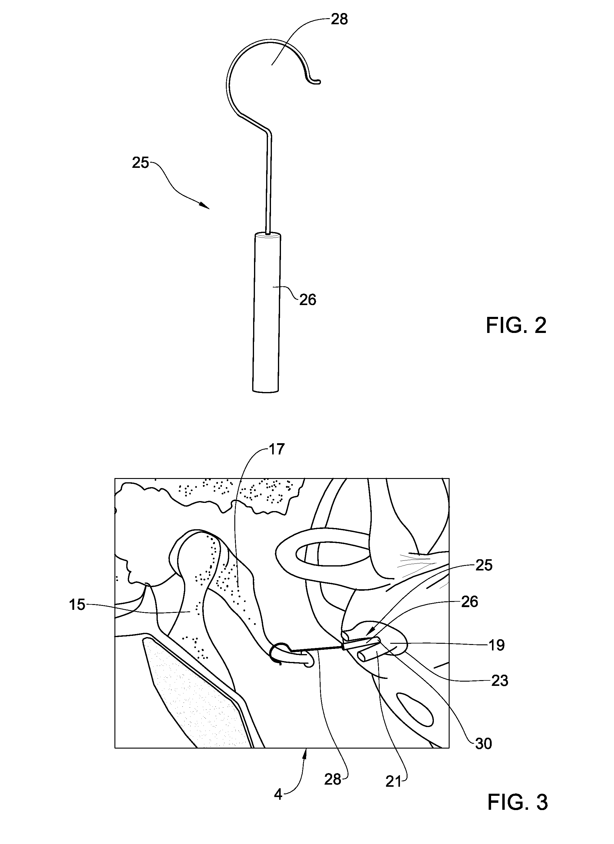
Furthermore, while attempting to bring the shaft 26 back to the desired position in the aperture 30, the surgeon can cause damage to the membrane of the oval window.

Method used


Image

  • Middle ear prosthesis
  • Middle ear prosthesis
  • Middle ear prosthesis

Examples


Embodiment Construction

[0035]FIG. 5A illustrates a middle ear prosthesis 40 comprising a shaft 42 having a distal end 44, for introducing into an aperture formed in a footplate portion of a stapes and in an oval window membrane. The shaft 42, here illustrated as a cylindrical piston, is configured for transmitting sound wave vibrations to the footplate and the membrane, and thereby to the inner ear. The prosthesis 40 further includes a coupling portion 46 for coupling thereof to one of the ossicles in the middle ear. The coupling portion 46 can be, for example, a hook or a wire crimp configured for coupling to one of the ossicles, for example, the incus, in such a way that sound vibrations therefrom are transferred to the shaft 42, and thereby to the inner ear. The coupling portion can include a strut to ease the handling of the prosthesis.

[0036]The prosthesis 40 further includes a stop member 48 spaced from the distal end 44 of the shaft 42. The stop member 48 is configured for bearing against the footpl...


PUM


Abstract

A middle ear prosthesis (40) is provided for mounting in the middle ear (4). The middle ear prosthesis comprises a shaft (42) having a distal end configured for the introduction into the inner ear (8) through an aperture (30) formed in a footplate (23) of a stapes bone and in a membrane of an oval window of the inner ear, by moving the shaft in an introduction direction, the shaft being configured for transmitting sound wave vibrations to the inner ear. The prosthesis further comprises a coupling portion (46), for coupling, the shaft to at least one of the ossicles (17) so as to allow transmitting thereby sound wave vibrations from the ossicles to the shaft; and a stop member (48) spaced from the distal end of the shaft and configured for bearing against the remaining portions thereby limiting the movement of the shaft in the introduction direction.

Description

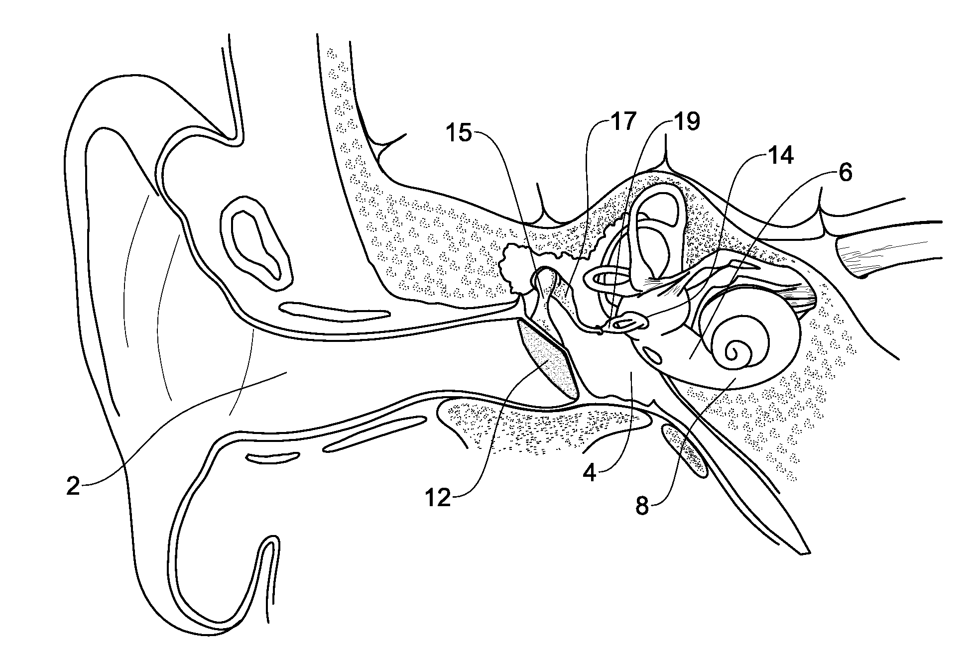
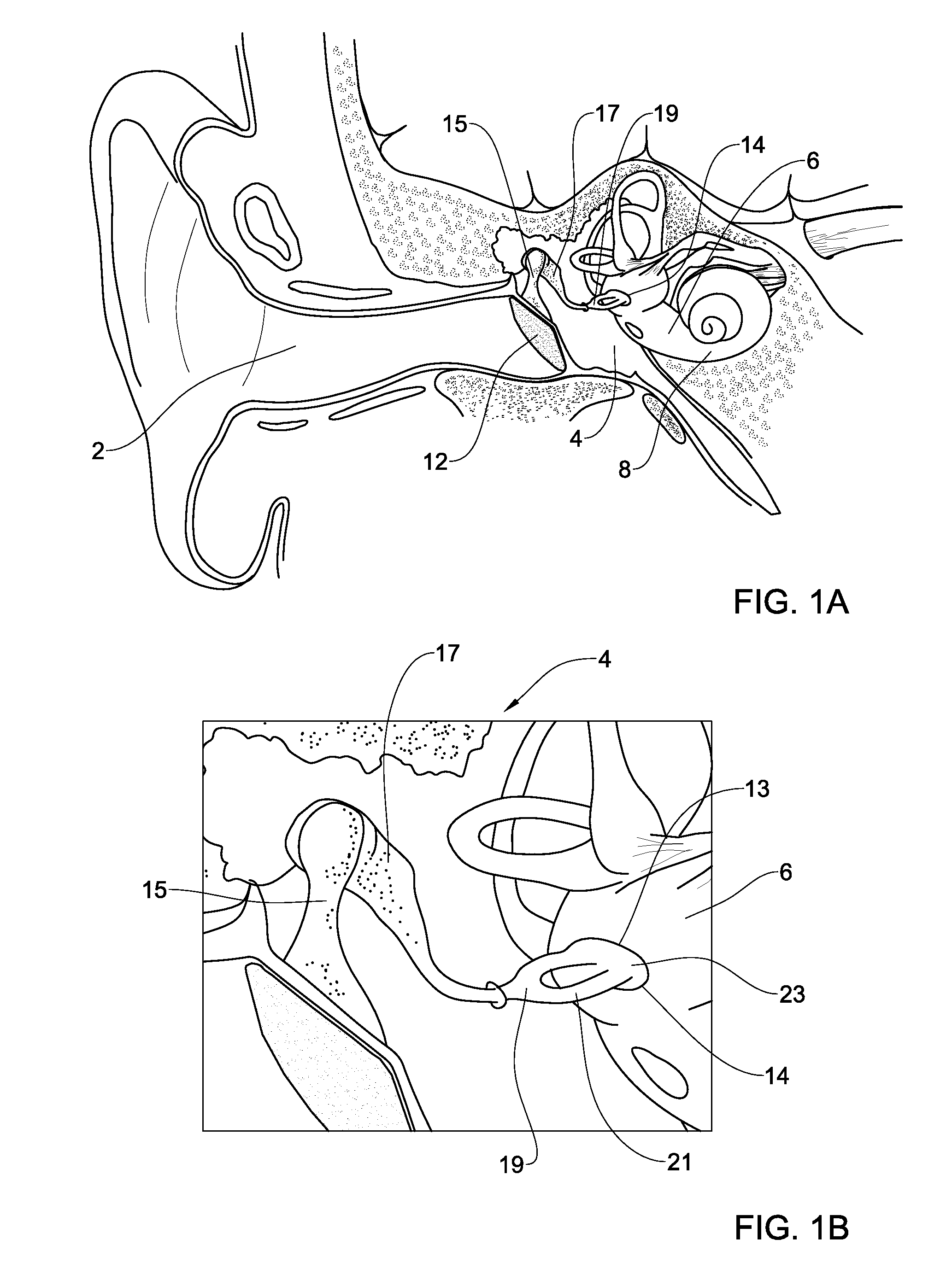
FIELD OF THE DISCLOSED SUBJECT MATTER[0001]This presently disclosed subject matter relates to a middle ear prosthesis. More particularly, the presently disclosed subject matter relates to a stapes prosthesis.BACKGROUND DESCRIPTION[0002]The anatomy and physiology of the ear is typically referred to as three parts: the outer ear, the middle ear and the inner ear, all of which are responsible for transmitting sound waves which are converted to neural activity to be sent to the brain through the auditory portion of the eighth cranial nerve.[0003]FIGS. 1A and 1B, show a cross section of the outer ear 2, the middle ear 4 and the inner ear 6. The middle ear 4 is the portion of the ear defined between the tympanic membrane 12 (typically referred to as the ‘eardrum’) and the oval window 14 of the cochlea 8 which is located in the inner ear 6. The cavity of the middle ear contains the three ossicles (bones) the malleus 15 (hammer), incus 17 (anvil), and stapes 19 (stirrup), which are coupled ...

Claims


Application Information

Patent Timeline
IPC IPC(8): A61F2/18
CPCA61F2002/183A61F2/18
Inventor MAZZAWI, SALIM
Owner MOR RES APPL LTD
Learn More