Isochronous wind turbine generator capable of stand-alone operation

a technology of isochronous wind turbines and generators, applied in the direction of electric generator control, machine/engine, dc-ac conversion without reversal, etc., can solve the problems of mechanical stress, limited control of power quality, and uncontrollable reactive power consumption

a technology of isochronous wind turbines and generators, applied in the direction of electric generator control, machine/engine, dc-ac conversion without reversal, etc., can solve the problems of mechanical stress, limited control of power quality, and uncontrollable reactive power consumption

US20150042092A1Inactive Publication Date: 2015-02-12SIEMENS AG

Image

  • Isochronous wind turbine generator capable of stand-alone operation
  • Isochronous wind turbine generator capable of stand-alone operation

Examples


Embodiment Construction

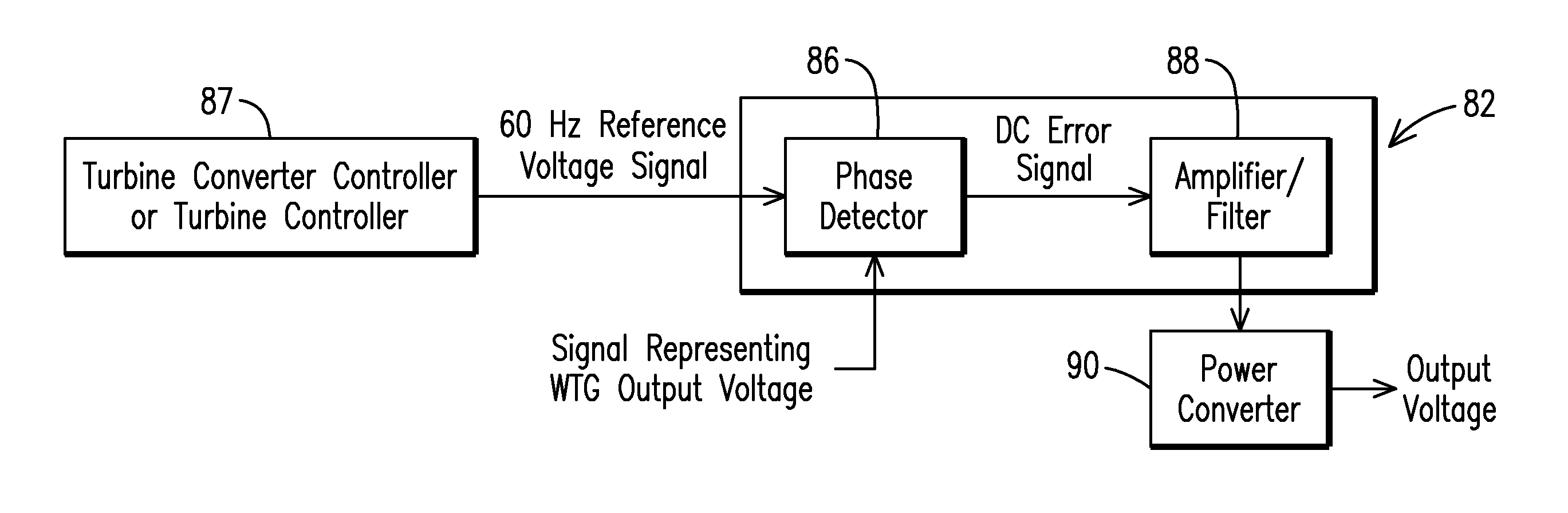
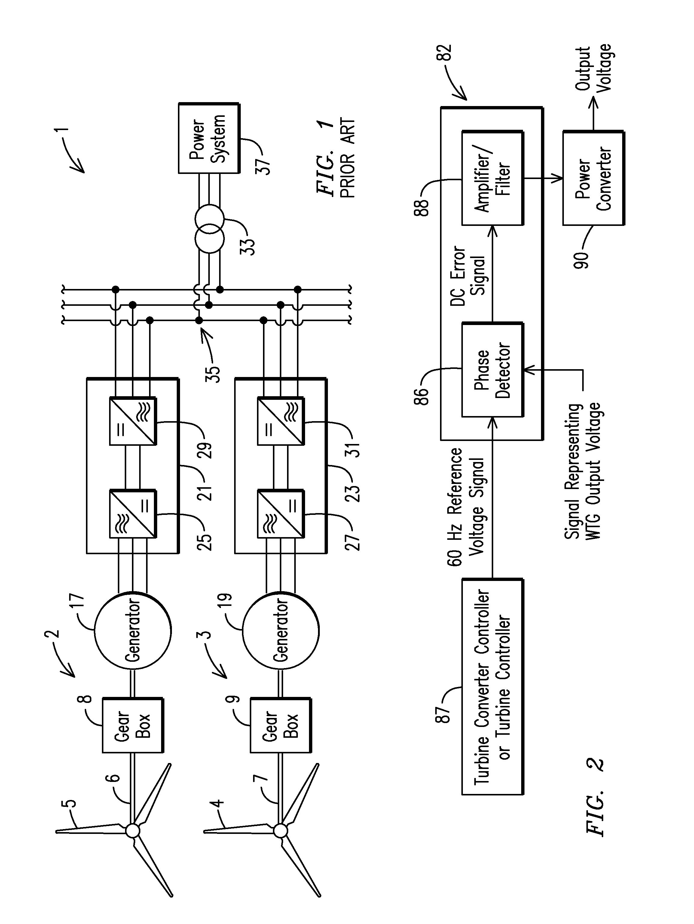
[0039]It is known in the prior art that a wind turbine generator (whether employing an induction generator or a synchronous generator) cannot “pick up” a load and supply electric power to it. Instead, the WTG must be associated with (e.g., coupled to) a power grid or power system to which one or more synchronous generators supply power. The prior art WTG converter measures the frequency of the grid voltage present at its output terminals then adjusts the phase angle of its output voltage to establish a desired phase angle difference δ, which in turn determines the power delivered to the grid according to the equations above.

[0040]Thus the prior art WTGs require the grid voltage as an input from which the grid voltage frequency can be determined. Given this requirement, prior art WTG's are not capable of stand-alone operation.

[0041]The present invention teaches a self-commutating WTG that has an inherent capability to operate in a stand-alone mode and thus operate isochronously. The ...


PUM


Abstract

A power generating device (2, 3) for supplying power to a power system (37). The power generating device includes a first component (87) for generating a first signal representing a frequency of a voltage on the power system, a power converter (90) for generating an output voltage, a second component (82) responsive to the first signal and to a second signal representing the output voltage, the second component producing an error signal representing a phase angle difference between the first and second signals, and the error signal being an input to the power converter for controlling the power converter to maintain the phase angle difference between the output voltage and the first signal.

Description

FIELD OF THE INVENTION[0001]The invention relates to wind turbines providing power to a load, and more particularly to wind turbines operating without synchronizing to a synchronous generator or a system voltage, but instead, synchronizing to an internally generated frequency signal.BACKGROUND OF THE INVENTION[0002]As is known in the art, wind energy can be converted to electrical energy with a wind turbine generator (WTG).[0003]Virtually all wind turbines are based on one of the three main wind turbine types:[0004]fixed speed WTGs with a direct grid-coupled (asynchronous) squirrel cage induction generator;[0005]variable speed WTGs with a doubly fed induction generator; and[0006]variable speed WTGs with a direct-drive synchronous generator.[0007]A fixed-speed WTG is typically connected to the grid through an induction (asynchronous) generator for generating real power. Wind-driven blades drive a blade rotor that in turn operates through a gear box (i.e., a transmission) to turn a ge...

Claims


Application Information

Patent Timeline
12 Feb 2015
Publication
US20150042092A1
IPC
F03D9/00; F03D7/04
CPC
F03D7/048; F03D9/005; H02J3/40; F03D9/257; H02J2300/28; H02J3/381; Y02E10/76; Y02E10/72
Inventors
NELSON, ROBERT J.; HAMMELSVANG, JESPER