Flow distributor

a distributor and flow technology, applied in the direction of mixers, cleaning of hollow articles, mixing methods, etc., can solve the problems of reducing the efficiency of the process unit modules in the cluster, increasing wear on the internal walls of the flow distributor, and loss of the efficiency of the process unit modules receiving multi-phase fluid or slurry

Active Publication Date: 2015-02-19
PROCESS DEV CENT
View PDF3 Cites 6 Cited by
  • Summary
  • Abstract
  • Description
  • Claims
  • Application Information

AI Technical Summary

Benefits of technology

[0009]a non-planar flow diverter positioned within the chamber so as to define a flow channel of varying cross-sectional area as measured in a plane orthogonal to the central longitudinal axis o

Problems solved by technology

However, problems can arise when the inlet stream is a multi-phase stream or slurry, because the solids phase separates into layers under the influence of gravity leading to a disproportional loading of the solids phase flow to each of the plurality of outlets, therefore reducing the effi

Method used


Image

  • Flow distributor
  • Flow distributor
  • Flow distributor

Examples


first embodiment

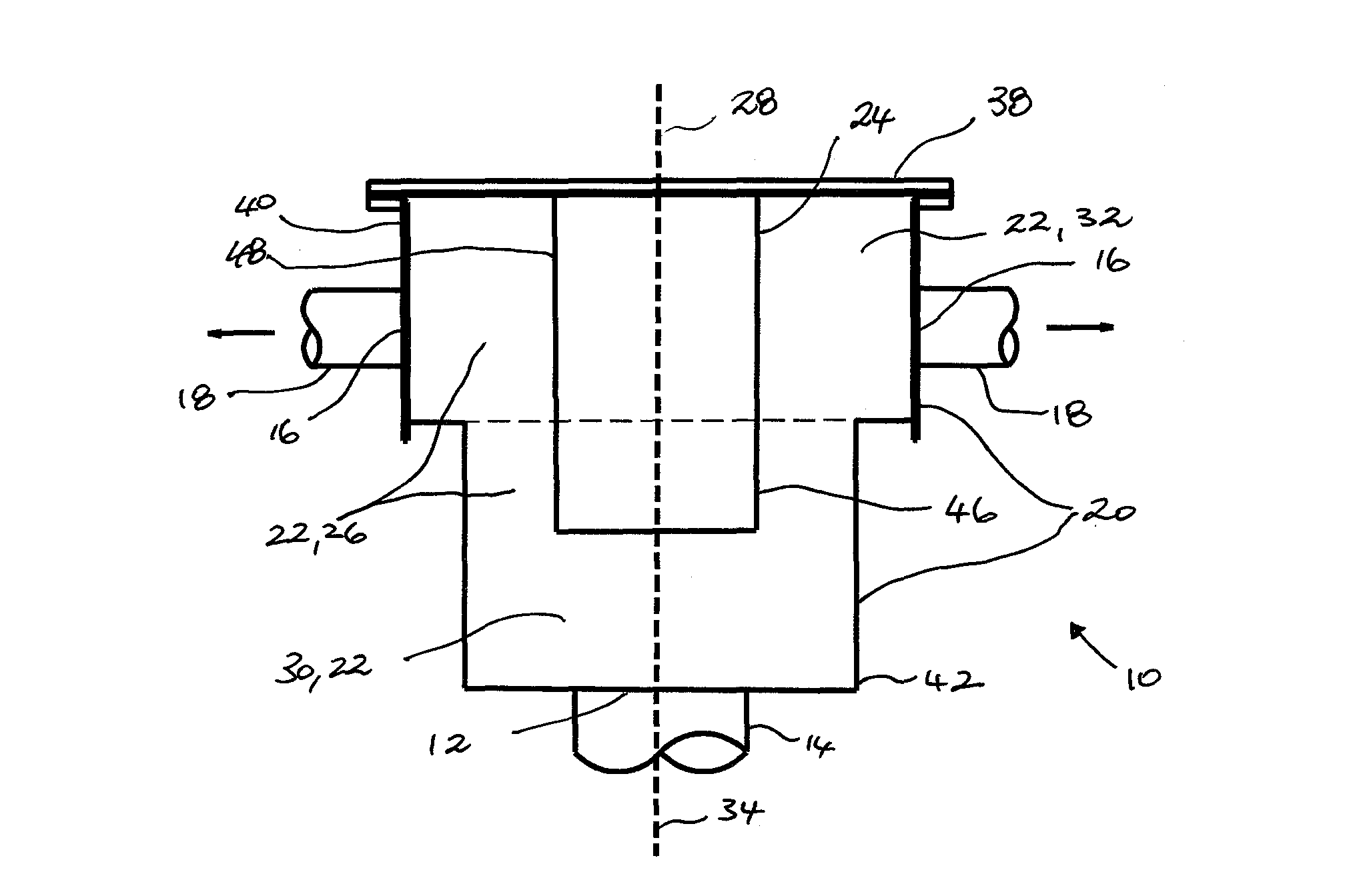
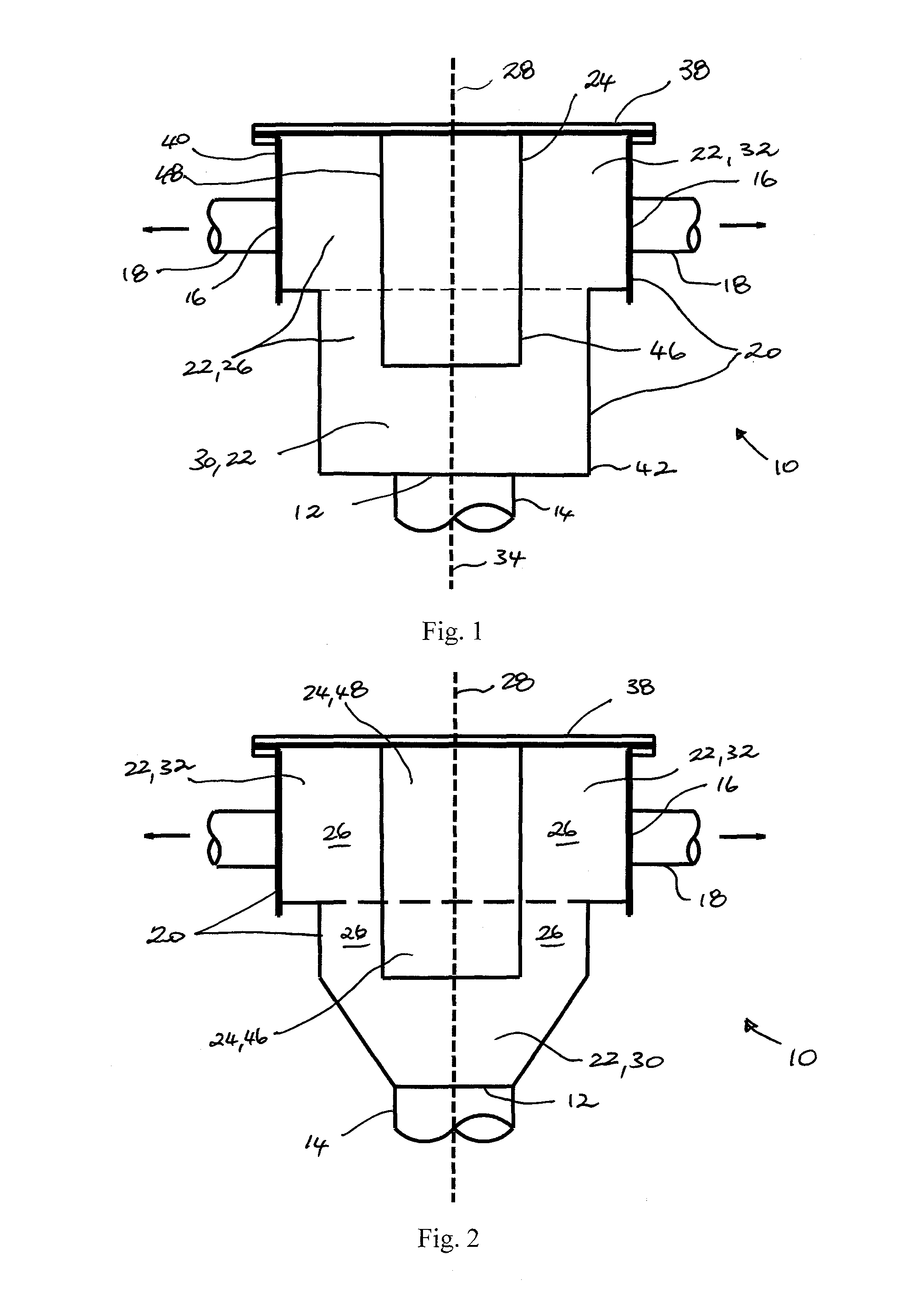
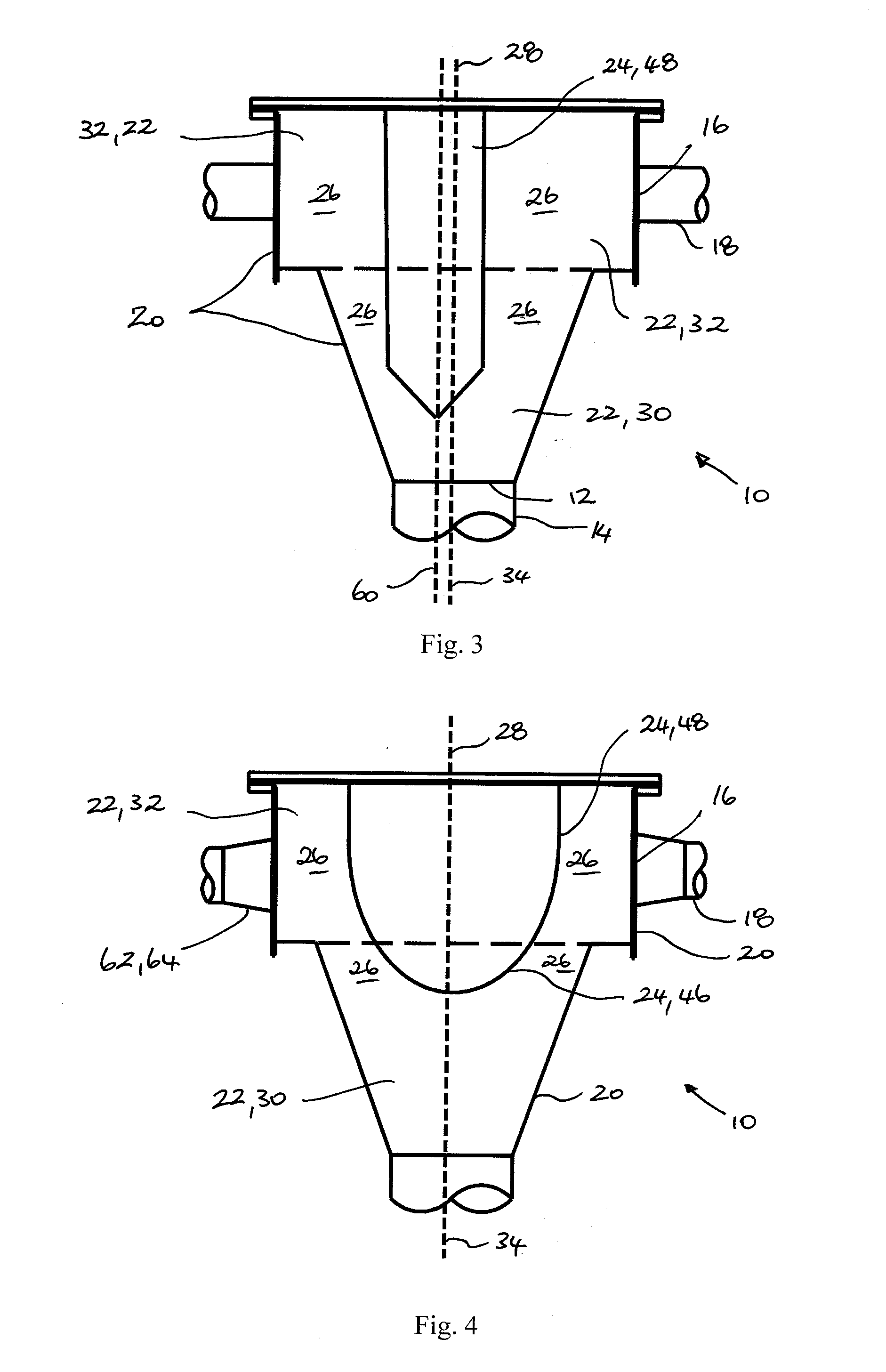
[0040]a flow distribution system for homogenization of a multi-phase fluid stream is now described with reference to Figure in which the flow distribution system is generally designated by the reference numeral 10. The system 10 includes an inlet 12 for receiving a multi-phase fluid stream from an inlet pipe 14 and a plurality of outlets 16 each for delivering a portion of the multi-phase fluid stream to a respective outlet pipe 18. The system 10 includes a hollow housing 20 forming an inner chamber 22 in fluid communication with the inlet 12 and the plurality of outlets 16. A non-planar flow diverter 24 is positioned within the chamber 22 so as to define a flow channel 26 of varying cross-sectional area for accelerating or decelerating the multi-phase fluid stream as it passes through the inner chamber to encourage turbulent mixing within the multi-phase fluid stream as it passes from the inlet to the plurality of outlets. When the multi-phase liquid stream encounters the flow dive...


PUM

PropertyMeasurementUnit
Angleaaaaaaaaaa
Angleaaaaaaaaaa
Angleaaaaaaaaaa

Abstract

A flow distribution system for a multi-phase fluid stream includes an inlet for receiving a multi-phase fluid stream from an inlet pipe, a plurality of outlets each for delivering a portion of the multi-phase fluid stream to a respective outlet pipe, and a hollow housing forming an inner chamber in fluid communication with the inlet and the plurality of outlets, where the housing has a central longitudinal axis. The inner chamber includes a first chamber portion adjacent to the inlet and a second chamber portion adjacent to the plurality of outlets, and the first chamber portion has a cross-sectional area that is less than the cross-sectional area of the second chamber portion. A non-planar flow diverter is positioned within the chamber.

Description

FIELD OF THE INVENTION[0001]The present invention relates to a flow distributor for distributing a multi-phase fluid or slurry from an inlet pipe to a plurality of outlet pipes.BACKGROUND[0002]It is common in mining, energy, chemical and related industries to process a multi-phase fluid stream or a slurry. It is often convenient and / or efficient to process the multi-phase fluid stream or slurry using a plurality of process unit modules arranged in a cluster. The number of process unit modules arranged in the cluster can range from two (2) to as many as thirty (30) units, or possibly more. Such process unit modules may include, by way of example, a separator for separating a solid phase from a gaseous phase, or for separating solid particles of different sizes or different density from a liquid phase.[0003]It is known in the art to use conventional flow distributors having an inlet arranged to receive an inlet stream of fluid from a common pipeline and a plurality of outlets for deli...

Claims


Application Information

Patent Timeline
IPC IPC(8): F17D1/00B01F23/00B01F23/30
CPCF17D1/005Y10T137/0402Y10T137/85938F25B41/48B01F25/4332B01F25/4336F16L41/021F16L41/023F28D2020/0069F25B39/028F16L41/03
Inventor DOIG, SCOTT GORDON
Owner PROCESS DEV CENT
Why Eureka
Try Eureka