
LED illumination module

a technology of led chip and illumination module, which is applied in the direction of point-like light source, semiconductor devices of light source, lighting and heating apparatus, etc., to achieve the effect of preventing degradation of fluorescent substances due to heat generated by led chips, reducing the cost of production, and easy changing of the color of emitted ligh

Inactive Publication Date: 2015-02-19
SEOUL SEMICONDUCTOR
View PDF22 Cites 33 Cited by
  • Summary
  • Abstract
  • Description
  • Claims
  • Application Information

AI Technical Summary

Benefits of technology

The present invention allows for easy changes in the color of emitted light by attaching and detaching a fluorescent substance plate to a heat sink. This also minimizes loss of optical efficiency by keeping the fluorescent substance plate at a predetermined distance from the LED chip. Additionally, degradation of the fluorescent substance due to heat generated by the LED chip can be prevented.

Problems solved by technology

Accordingly, an additional secondary lens is needed to obtain an orientation angle of about 180° or more, and there was a burden of preparing an additional support unit configured to locate the lens at a sufficient height from the ground.

Method used


Image

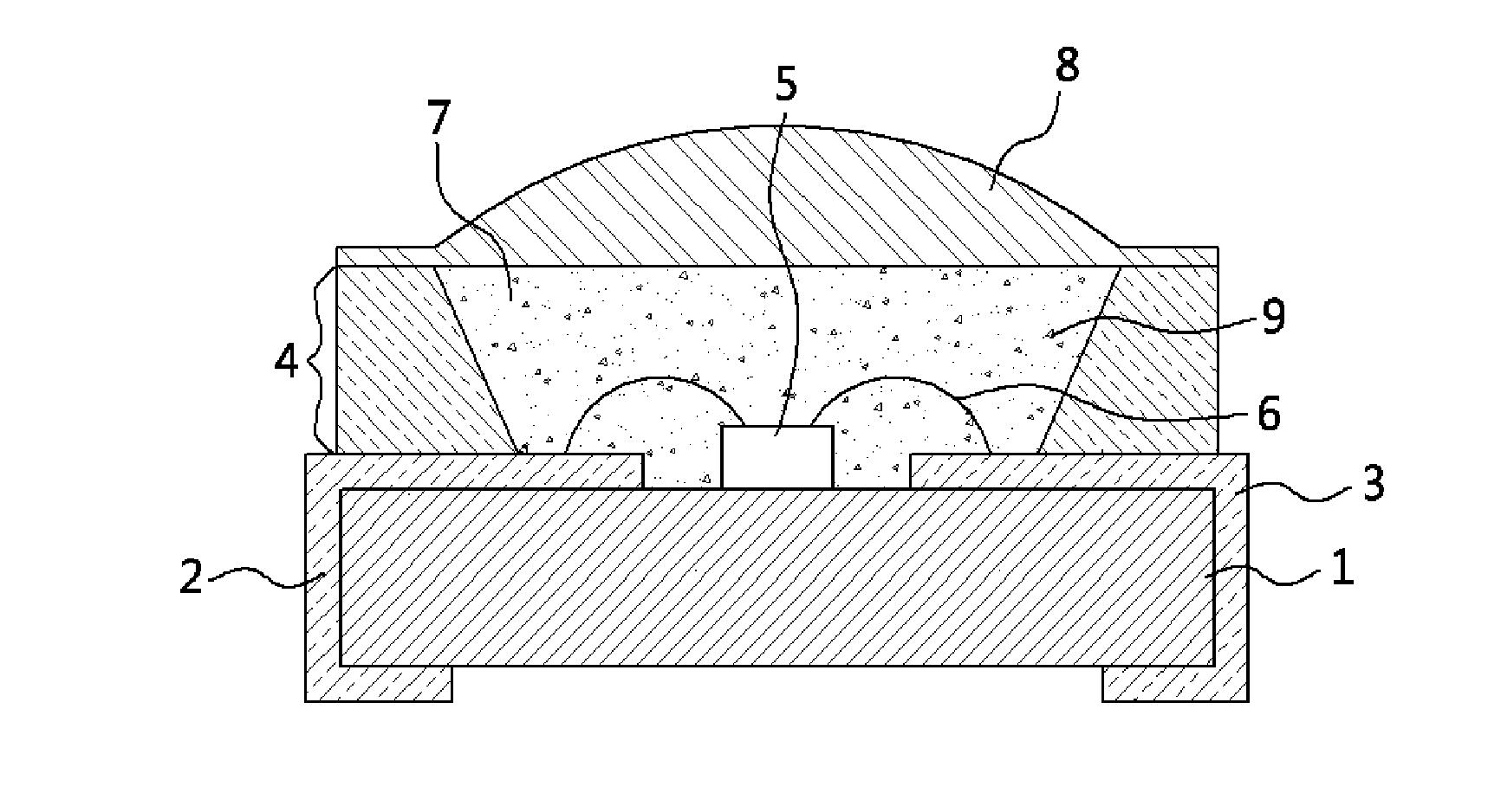
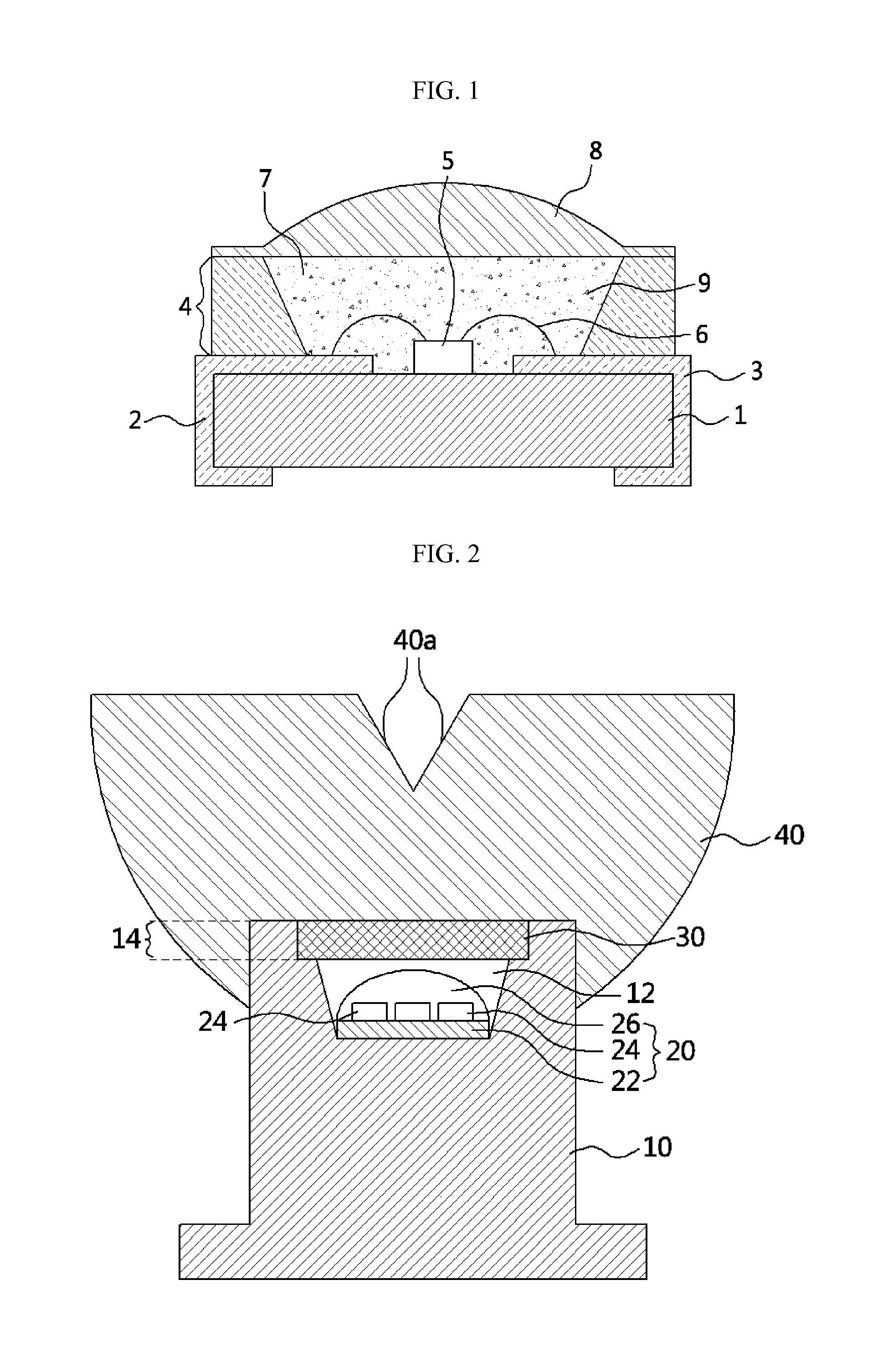
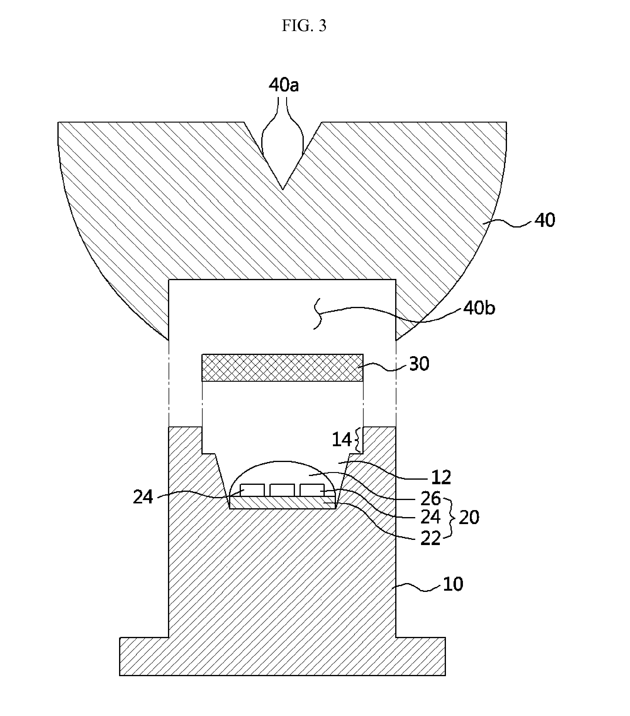
  • LED illumination module
  • LED illumination module
  • LED illumination module

Examples


Embodiment Construction

[0026]Hereinafter, exemplary embodiments of the present invention will be described in detail. It should be understood, however, that there is no intent to limit the invention to the particular forms disclosed. On the contrary, the invention is to cover all modifications, equivalents, and alternatives falling within the spirit and scope of the claims.

[0027]It will be understood that when a layer is referred to as being “on” another layer or substrate, it can be directly on the other layer or substrate or intervening layers may also be present. Terms that describe spatial relationships, such as “beneath,”“below,”“lower,”“above,”“upper” and the like, may be used herein for ease of description to describe one element or feature's relationship to another element(s) or feature(s) as illustrated in the figures. It will be understood that such terms are intended to encompass different orientations of the device in use or operation in addition to the orientation(s) depicted in the figures. ...


PUM


Abstract

Provided is a light emitting diode (LED) illumination module. The LED illumination module includes a fluorescent substance plate mounted to be capable of being attached to and detached from an opening formed in a top surface of a heat sink. Also, the LED illumination module includes a lens that covers the opening of the heat sink and is mounted to be capable of being attached to and detached from the heat sink.

Description

CROSS-REFERENCE TO RELATED APPLICATIONS[0001]This application is the National Stage of International Application No. PCT / KR2013 / 002050, filed on Mar. 14, 2013, and claims priority from and the benefit of Korean Patent Application No. 10-2012-0026275, filed on Mar. 14, 2012, which are hereby incorporated by reference for all purposes as if fully set forth herein.BACKGROUND[0002]1. Field[0003]The present invention relates to an illumination module, and more particularly, to a light emitting diode (LED) illumination module mounted integrally with a heat sink.[0004]2. Discussion of the Background[0005]Since light emitting diodes (LEDs) have many advantages, such as environmental friendliness, a long lifespan, low power consumption, and high luminous efficiency, the application range of LEDs has gradually expanded with recent developments of semiconductor technology. In particular, with the recent commercialization of high-luminance white LEDs, various attempts to adopt the high-luminanc...

Claims


Application Information

Patent Timeline
Patent Type & Authority Applications(United States)
IPC IPC(8): F21V13/02H01L33/52H01L33/50F21K99/00F21V29/00F21V17/12
CPCF21V13/02F21V29/2212F21V17/12F21Y2101/02F21K9/50H01L33/52H01L33/50F21V5/04F21V7/0091F21V29/74F21K9/64F21Y2115/10F21K9/60H01L2224/48091H01L2924/181H01L2924/00014H01L2924/00012
Inventor JUNG, JUNG HWAKIM, EUN JUJUNG, SEOUNG HO
Owner SEOUL SEMICONDUCTOR
Learn More