Rolling bearing

a technology of rolling bearings and rollers, which is applied in the direction of roller bearings, mechanical equipment, rotary machine parts, etc., can solve the problems of increasing the roughness of the surface of the gear, the wear of the rollers in the pockets, and the increase of the roughness of the gear, so as to improve the axial flow of lubricant oil and prolong the life

Inactive Publication Date: 2015-02-19
NTN CORP
View PDF4 Cites 0 Cited by
  • Summary
  • Abstract
  • Description
  • Claims
  • Application Information

AI Technical Summary

Benefits of technology

[0027]According to the roller bearing offered by the present invention, there is an improved axial flow of lubricant oil from an inner diameter side of the retainer toward the cutout which is formed in the annular region. Therefore, it is less likely that dust such as metal abrasion powder contained in the lubricant oil will stay at the inner-side projection of the pillar.
[0028]Hence, rolling bearings according to the present invention are less subject to such problems as indentations and loss of oil film from roller surfaces, and has a longer life even when used in planetary gear reduction apparatuses which are prone to produce metal abrasion powder.

Problems solved by technology

As a result, there has been a problem that the rollers 26 in the pockets 28 wear quickly due to abrasion with the dust, and particularly with metal abrasion powder such as steel powder, which has accumulated at the inner-side projections 31 and the outer-side projections 32.
Especially in recent years, manufacturers of the reduction gear apparatuses are trying to reduce their cost by reducing steps in gear finishing processes for example, so the gears have an increased surface roughness, and there have been many cases where meshing gears have removed surface roughness projections, producing a large amount of abrasion powder.

Method used


Image

  • Rolling bearing
  • Rolling bearing
  • Rolling bearing

Examples


Embodiment Construction

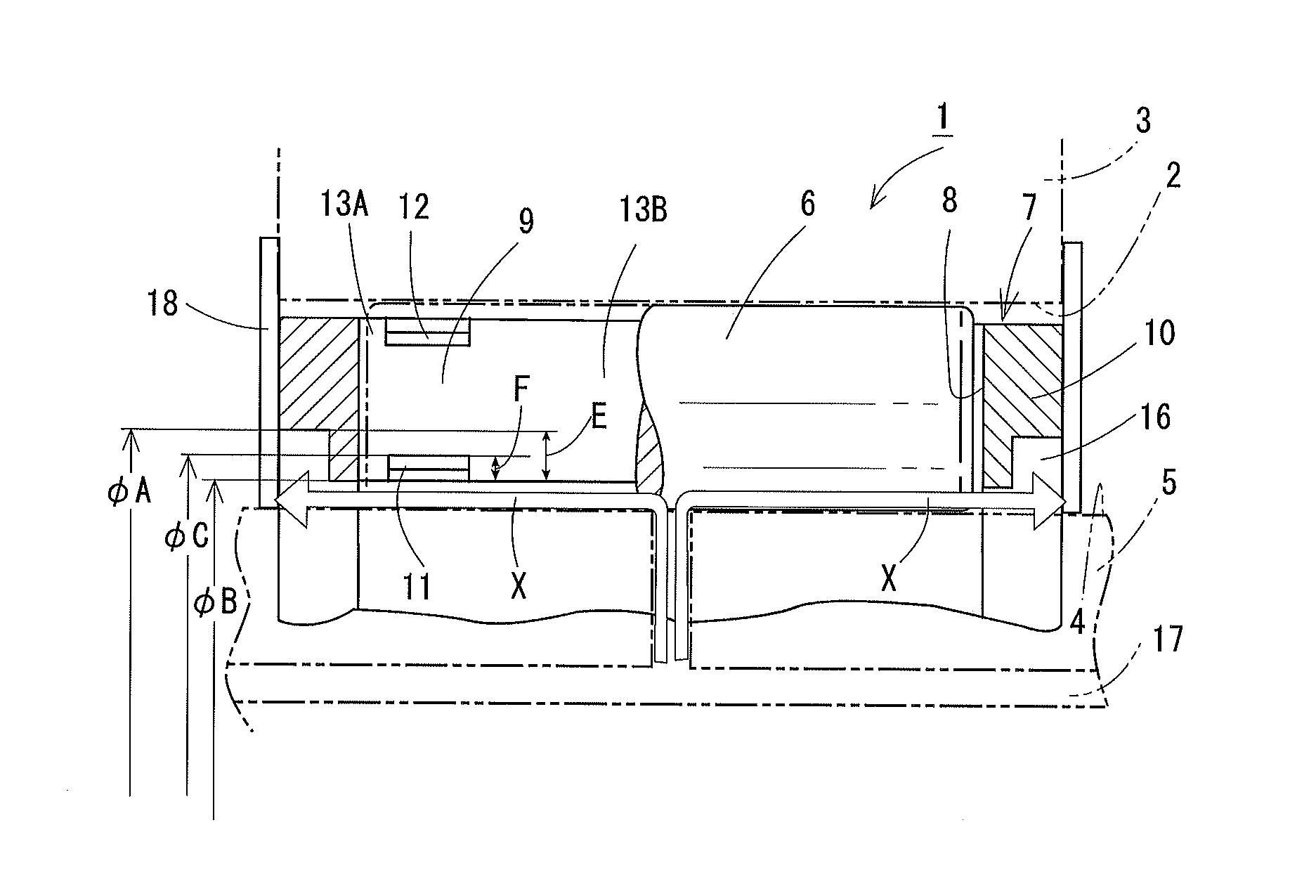
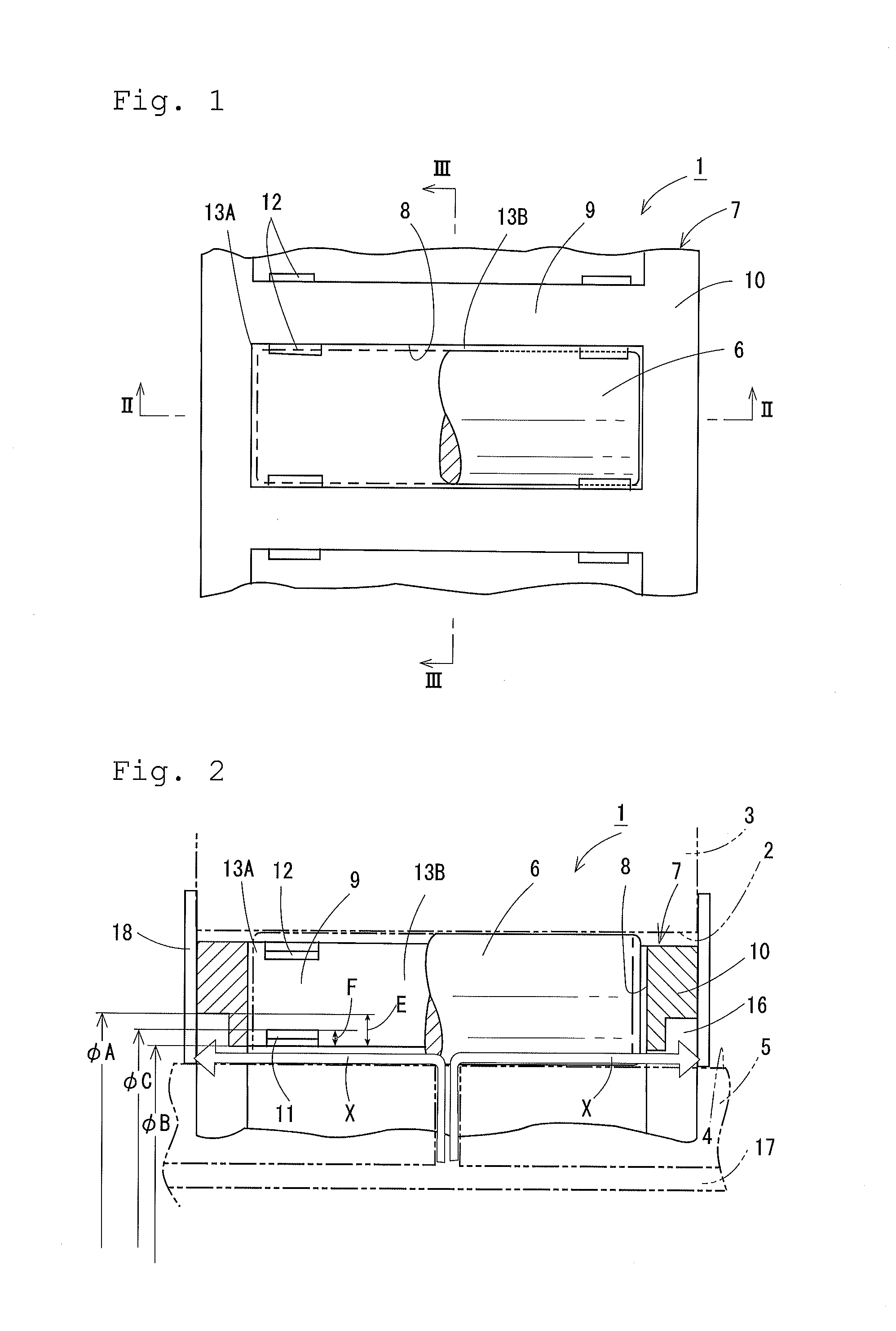
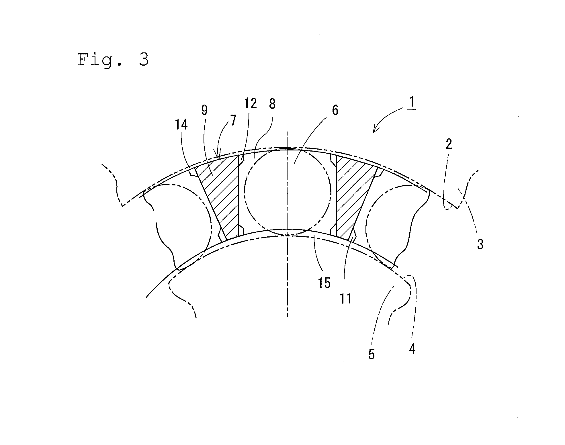
[0035]Embodiments of the present invention will be described based on FIG. 1 through FIG. 3.

[0036]A roller bearing 1 comprises an outside member 3 which includes an inner circumferential surface having a cylindrical outer ring track 2; an inside member 5 which includes an outer circumferential surface having a cylindrical inner ring track 4; and a plurality of rollers 6 which are rotatable between these outer ring track 2 and the inner ring track 4.

[0037]The rollers 6 are cylindrical bodies made of a metal material for example, formed as needle rollers, long cylindrical rollers, etc., and entirely encased in a cylindrical retainer 7, forming an array of a uniform interval.

[0038]The retainer 7, formed of a resin material by means of injection molding for example, has rectangular pockets 8 at a predetermined interval from one to another in a circumferential direction for housing the rollers 6 in the uniform interval. The retainer 7 is penetrated by the pockets 8 from a radially inner ...


PUM

PropertyMeasurementUnit
inner diameteraaaaaaaaaa
diametrical dimensionaaaaaaaaaa
outer diameteraaaaaaaaaa

Abstract

An object of the present invention is to prevent abrasion powder from accumulating and stacking in pockets in a retainer of a roller bearing, thereby protecting the rollers from brinelling and loss of lubrication for extended life of the roller bearing. On an inner diameter surface of annular regions in the retainer, cutouts are formed from the retainer's axially outer side end surface toward an inner side. The cutout has an outer diametrical position on a more radially outer position than an outer diametrical end of the inner-side projection of the retainer. This improves an axial flow of lubricant oil from an inner diameter side of the retainer toward the cutout which is formed in the annular region, making it less likely that dust such as metal abrasion powder contained in the lubricant oil will stay at the inner-side projection of the pillar.

Description

TECHNICAL FIELD[0001]The present invention relates to rolling bearings suitably applicable to planetary gear reduction apparatuses.BACKGROUND ART[0002]As shown in FIG. 4 through FIG. 6, a roller bearing 21 comprises an outside member 23 which includes an inner circumferential surface having a cylindrical outer ring track 22; an inside member 25 which includes an outer circumferential surface having a cylindrical inner ring track 24; and a plurality of rollers 26 which are rotatable between these outer ring track 22 and the inner ring track 24.[0003]The rollers 26 are held rotatably by a retainer 27 which is formed into a cylindrical shape as a whole. The retainer 27 has pockets 28 for housing the rollers 26 at a predetermined interval in a circumferential direction; pillars 29 between the pockets 28 which are mutually adjacent in the circumferential direction; and annular portions 30 at both axial sides of the pillar 29.[0004]The pillar 29 of the retainer 27 has inner-side projectio...

Claims


Application Information

Patent Timeline
Patent Type & Authority Applications(United States)
IPC IPC(8): F16C33/46F16C19/26
CPCF16C19/26F16C33/46F16C33/6651F16C33/4617F16C33/4635F16C33/4676F16C2208/58F16C2208/62F16C2240/42F16C2240/70F16C2361/61F16C2240/44
Inventor NAKAGAWA, TSUTOMUNISHIMURA, MASASHIOISHI, SHINJI
Owner NTN CORP
Why Eureka
Try Eureka