Braided flow diverter using flat-round technology

a technology of braided flow and diverter, applied in the field of vascular implants, can solve the problems of not maximizing the amount of vessel area coverage provided by such braided flow diverting stents, and achieve the effects of reducing total wall thickness, increasing the area coverage of the vessel wall, and significant wall thickness

Active Publication Date: 2015-10-22
DEPUY SYNTHES PROD INC
View PDF3 Cites 0 Cited by
  • Summary
  • Abstract
  • Description
  • Claims
  • Application Information

AI Technical Summary

Benefits of technology

[0004]Briefly and in general terms, the present invention provides for a generally tubular braided flow diverting stent formed of alternating round and rectangular elongated members, for treatment of aneurysms. The generally tubular braided flow diverting stent can be utilized to redirect blood flow away from a neck of an intracranial aneurysm, or to define a new luminal flow path through a fusiform aneurysm. The generally tubular braided flow diverting stent maintains a significant wall thickness while increasing area coverage of a vessel wall. The sliding of round elongated members over rectangular elongated members also provides very low crimped diameters to allow delivery of the braided flow diverting stent in narrow portions of the vasculature. Total wall thickness is reduced compared to a braided stent having a similar vessel wall coverage using only round wires. Axial flow disruption is improved compared to a braid of similar vessel wall coverage using only flat wires.

Problems solved by technology

While the use of round wires in forming such braided flow diverting stents typically provide a maximal wall-thickness for their construction, the amount of vessel area coverage provided by such braided flow diverting stents is not maximized.

Method used


Image

  • Braided flow diverter using flat-round technology
  • Braided flow diverter using flat-round technology

Examples


first embodiment

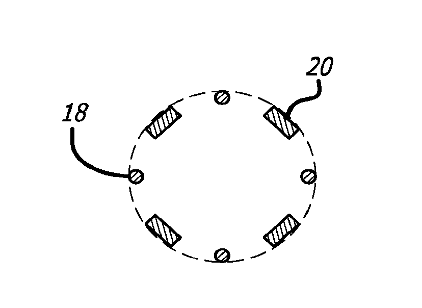
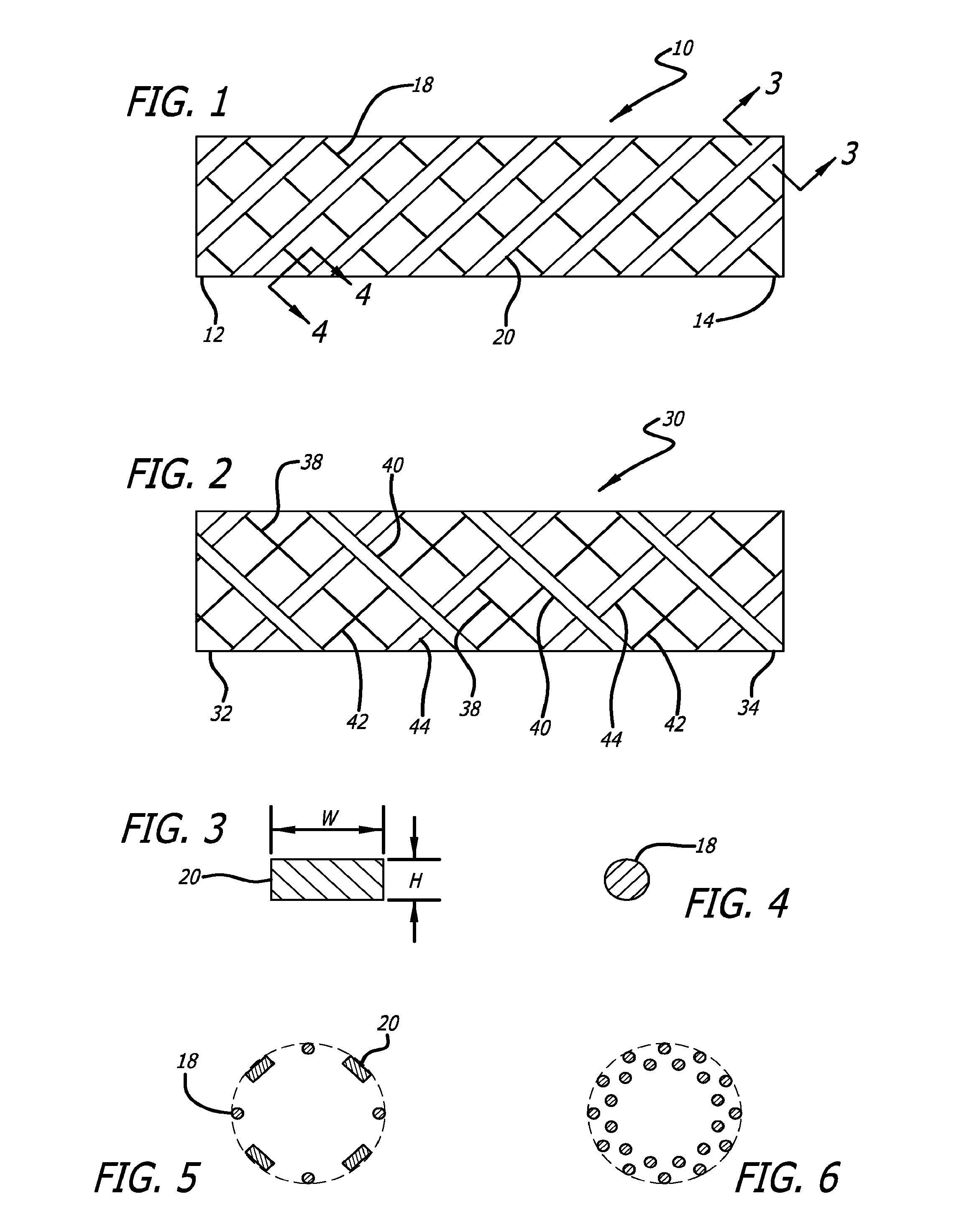
[0017]Referring to the drawings, which are provided by way of example, and not by way of limitation, in a first embodiment, illustrated in FIG. 1, the present invention provides for a generally tubular braided flow diverting stent 10 for treatment of aneurysms, having a proximal end 12, a distal end 14, and an inner lumen (not shown). The generally tubular braided flow diverting stent is preferably formed from a plurality of elongate members, is typically formed from two or more metal wires, or polymeric fibers or strands of material, for example. In a presently preferred aspect, the tubular braided stent optionally may be a self-expanding stent, formed to have a compressed configuration and an expanded configuration. In another presently preferred aspect, the tubular braided stent optionally may be formed of a shape memory material such as a nickel-titanium alloy, for example, having a shape memory position in the expanded configuration. For example, the tubular braided stent may b...

second embodiment

[0023]In a second embodiment, illustrated in FIG. 2, in which like elements are indicated by like reference numbers, the present invention provides for a generally tubular braided flow diverting stent 30 for treatment of aneurysms. The tubular braided flow diverting stent has a proximal end 32, a distal end 34, and an inner lumen (not shown), and is preferably formed from a plurality of elongate members, typically formed from two or more metal wires, or polymeric fibers or strands of material, for example. In one presently preferred aspect, the tubular braided stent optionally may be a self-expanding stent, formed to have a compressed configuration and an expanded configuration. The tubular braided flow diverting stent can be formed of a shape memory material such as a nickel-titanium alloy, for example, having a shape memory position in the expanded configuration. For example, the tubular braided flow diverting stent may be appropriately heat treated so that the tubular braided flo...


PUM


Abstract

A generally tubular braided flow diverting stent is formed of alternating round and rectangular elongated members, for treatment of aneurysms. The generally tubular braided flow diverting stent maintains a significant wall thickness while increasing area coverage of a vessel wall. Sliding of the round elongated members over the rectangular elongated members allows the stent to be crimped to very low diameters for delivery in narrow portions of the vasculature.

Description

BACKGROUND OF THE INVENTION[0001]This invention relates generally to a vascular implant that can be used for treatment of aneurysms, and more particularly concerns a braided flow diverter using flat-round technology to divert flow away from an entrance or neck of an intracranial aneurysm or to define a new luminal flow path through a fusiform aneurysm, as an alternative or supplement to delivery of an embolic coil within such an aneurysm.[0002]Braided stents are typically formed from a plurality of elongate members, such as two or more metal wires, or polymeric fibers or strands of material, for example, and can be very useful in treatment of neurovascular defects. Braided flow diverting stents are commonly constructed from round wires. While the use of round wires in forming such braided flow diverting stents typically provide a maximal wall-thickness for their construction, the amount of vessel area coverage provided by such braided flow diverting stents is not maximized. Braided ...

Claims


Application Information

Patent Timeline
Patent Type & Authority Applications(United States)
IPC IPC(8): A61F2/88A61B19/00A61F2/90
CPCA61F2/885A61F2/90A61B19/54A61B2019/5466A61F2230/0006A61F2230/0019A61F2250/0028A61F2002/823A61F2250/0036A61F2230/0008A61B90/39A61B2090/3966D04C1/06D10B2509/06A61F2/88
Inventor SLAZAS, ROBERTLORENZO, JUAN A.
Owner DEPUY SYNTHES PROD INC
Why Eureka
Try Eureka