Cutting tool

Inactive Publication Date: 2015-02-19
SUMITOMO ELECTRIC HARDMETAL CORP
View PDF5 Cites 2 Cited by
  • Summary
  • Abstract
  • Description
  • Claims
  • Application Information

AI Technical Summary

Benefits of technology

The present invention offers a cutting tool that uses a polygonal-shaped cutting insert with five to eight corners, providing a large number of usable corners and reducing cost per corner. Additionally, the outer peripheral surface of the cutting insert serves as a rake face, increasing the side cutting edge angle and reducing the need for a nose-radius at each corner, leading to improved cutting force and machining stability, accuracy, and life of the cutting insert. Furthermore, when the cutting insert is used in vertical orientation, the rigidity of the cutting insert can be increased.

Problems solved by technology

However, there are no cutting inserts having a regular polygonal shape with five or more corners for, for example, cutting tools for turning.

Method used


Image

  • Cutting tool
  • Cutting tool
  • Cutting tool

Examples


Embodiment Construction

[0030]Cutting tools according to embodiments of the present invention will now be described with reference to FIGS. 1 to 12.

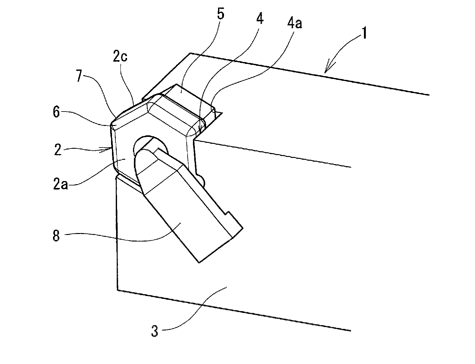
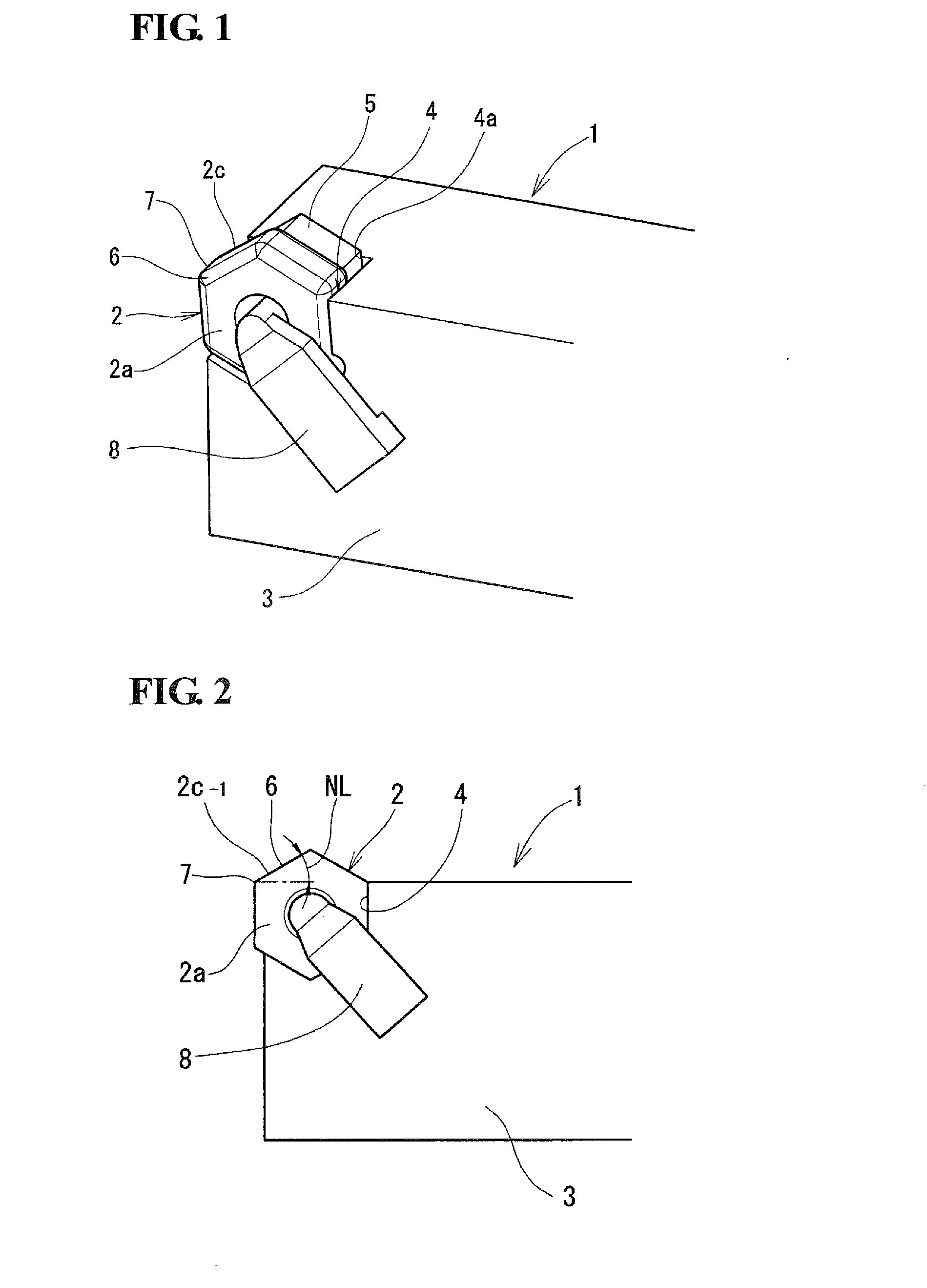
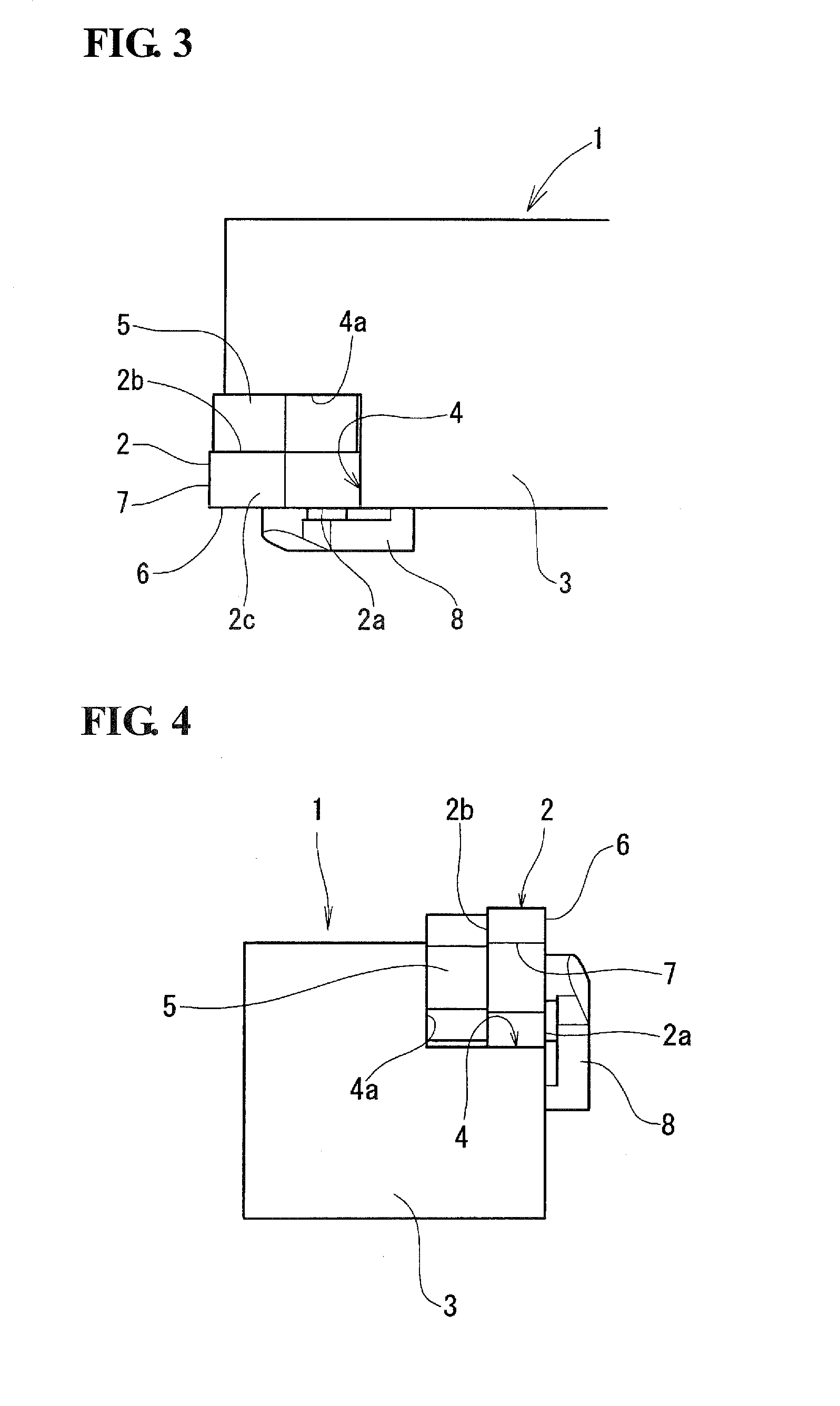
[0031]A cutting tool 1 illustrated in FIGS. 1 and 2 is a cutting tool for turning. The cutting tool 1 includes a cutting insert 2 having a regular polygonal shape. Here, the cutting insert 2 is a negative-type cutting insert having a regular hexagonal shape in which an outer peripheral surface 2c is orthogonal to top and bottom surfaces 2a and 2b. The cutting insert 2 is detachably attached to a support seat 4 provided at an end of a tool holder 3.

[0032]The support seat 4 is formed by cutting into a side surface of the tool holder 3 in a width direction of the holder at a corner where the side surface, a top surface, and a front surface of the tool holder 3 meet. A main seat surface 4a of the support seat 4 extends vertically. A plank 5 is placed on the main seat surface 4a of the support seat 4, and the cutting insert 2 is seated on the plank 5.

[0033]The cutti...


PUM

PropertyMeasurementUnit
Angleaaaaaaaaaa
Stiffnessaaaaaaaaaa

Abstract

A cutting tool including a cutting insert for which corner changing can be performed, the cutting tool having a large number of usable corners and thereby being cost effective, reducing cutting force during machining, and ensuring high rigidity. A negative-type cutting insert having a regular polygonal shape with five to eight corners is attached to an end of a tool holder such that one of two adjacent sides of an outer peripheral surface serves as a rake face having a negative rake angle, the other of the two adjacent sides serves as a front flank face, a ridge between the two adjacent sides of the outer peripheral surface serves as an end cutting edge, and a ridge between the side that serves as the rake face and one of top and bottom surfaces serves as a side cutting edge, and such that corner changing can be performed.

Description

TECHNICAL FIELD[0001]The present invention relates to cutting tools, such as cutting tools for turning, formed by attaching a cutting insert, for which corner changing can be performed, to a tool holder. More particularly, the present invention relates to a cutting tool which has a large number of usable corners and is thereby cost effective, which reduces cutting force during machining, and which ensures high rigidity.BACKGROUND ART[0002]Some known cutting inserts have five or more corners. For example, PTL 1 given below discloses a heptagonal cutting insert.[0003]With a cutting insert for which corner changing can be performed, as the number of corners increases, the cost per corner decreases and the economic advantage increases. However, there are no cutting inserts having a regular polygonal shape with five or more corners for, for example, cutting tools for turning.CITATION LISTPatent Literature[0004]PTL 1: Japanese Unexamined Patent Application Publication No. 2008-23660SUMMAR...

Claims


Application Information

Patent Timeline
IPC IPC(8): B23B27/16B23B27/14
CPCB23B27/1607B23B27/148B23B27/1611B23B2200/3609B23B2226/31B23B2200/087B23B2226/125B23B27/145B23B2200/0404B23B2200/128B23B2200/283B23B2200/369B23B2200/0438B23B2200/0457B23B2200/242B23B2200/245B23B2226/315Y10T407/2268
Inventor TANAKA, KUNISHIGEUESAKA, SHINYAOKAMURA, KATSUMI
Owner SUMITOMO ELECTRIC HARDMETAL CORP
Why Eureka
Try Eureka