Methods and systems for vehicle driveline torque estimation

a technology of driveline torque and estimation method, which is applied in the field of system and methods for estimating driveline torque, can solve the problems of driver demand torque greater than or less, engine torque that is estimated solely based on engine speed and load, and may not be as accurate as is desired, etc., to improve transmission shifting, improve engine torque estimation, and improve the effect of engine torque estimation

Active Publication Date: 2015-02-19
FORD GLOBAL TECH LLC
View PDF6 Cites 6 Cited by
  • Summary
  • Abstract
  • Description
  • Claims
  • Application Information

AI Technical Summary

Benefits of technology

[0005]By estimating torque transferred across a dual mass flywheel based on spring deflection, it may be possible to provide the technical result of an improved estimate of engine torque. The improved estimate of engine torque may be the basis for making engine torque adjustments so that driveline torque more closely matches driver demand torque. Additionally, an improved estimate of engine torque as determined from a dual mass flywheel may improve transmission shifting, driveline disconnect clutch operation, and operation of other driveline systems or components that rely on engine torque to provide their desired function.
[0006]The present description may provide several advantages. Specifically, the approach may improve hybrid driveline operation. For example, transmission shifting may be improved via having an improved engine torque estimate. Further, the approach may improve engine starting via providing an engine torque estimate while the engine is starting. Further still, the approach may allow for improved engine torque control.

Problems solved by technology

However, it may be challenging to provide an accurate estimate of driveline torque produced by the engine to meet the driver demand torque.
For example, an engine torque that is estimated solely based on engine speed and load may not be as accurate as is desired due to varying fuel composition, manufacturing tolerances in engine components, system errors (e.g., cam positioning errors), and other conditions that may affect engine torque.
Consequently, errors estimating the driveline torque (e.g., a sum of engine and motor torque) may result in a driver demand torque that is greater than or less than a desired driver demand torque.
As a result, transmission shifting, driveline disconnect operation, and capability of providing an accurate driver demand torque may degrade.

Method used


Image

  • Methods and systems for vehicle driveline torque estimation
  • Methods and systems for vehicle driveline torque estimation
  • Methods and systems for vehicle driveline torque estimation

Examples


Embodiment Construction

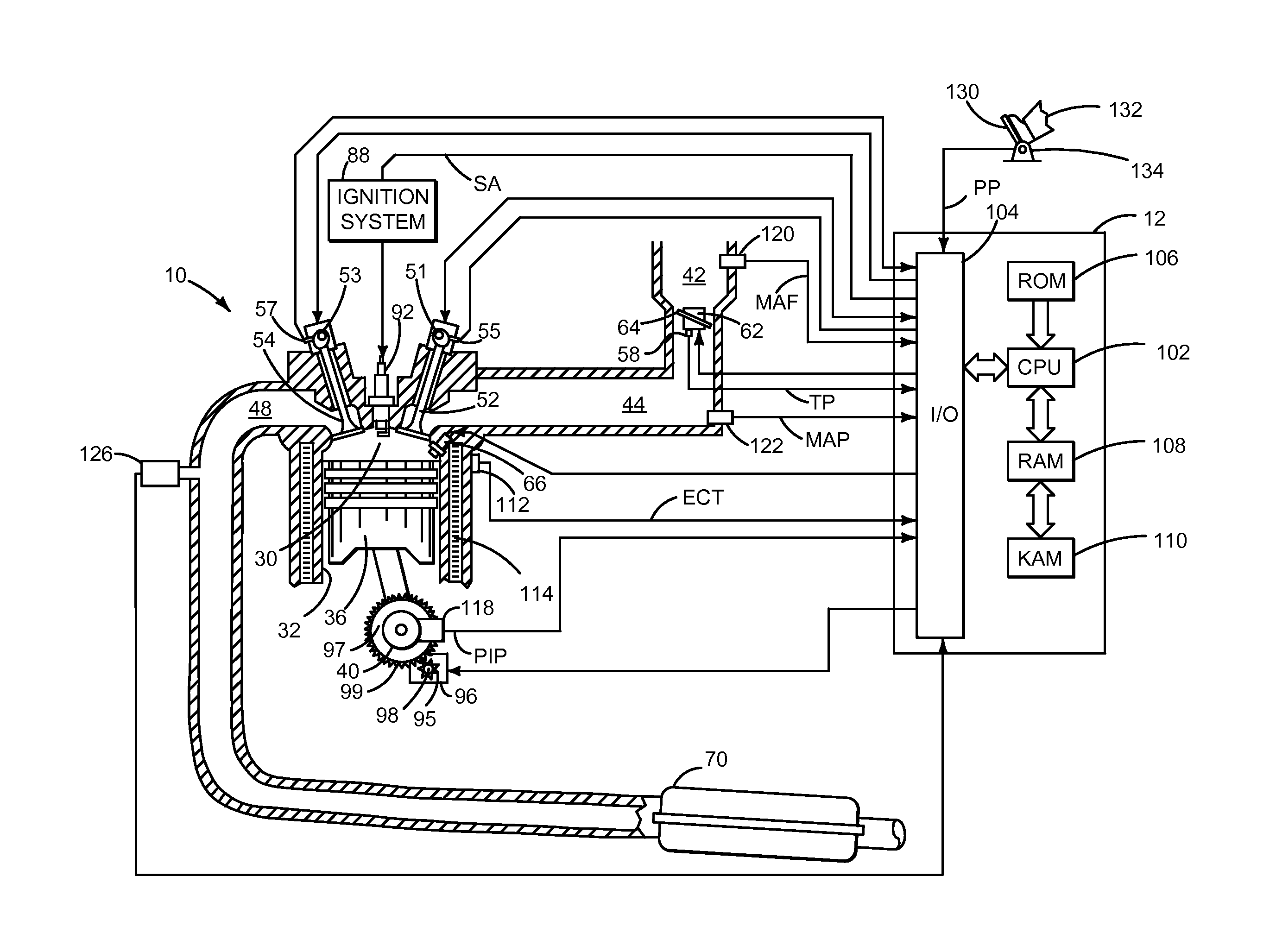
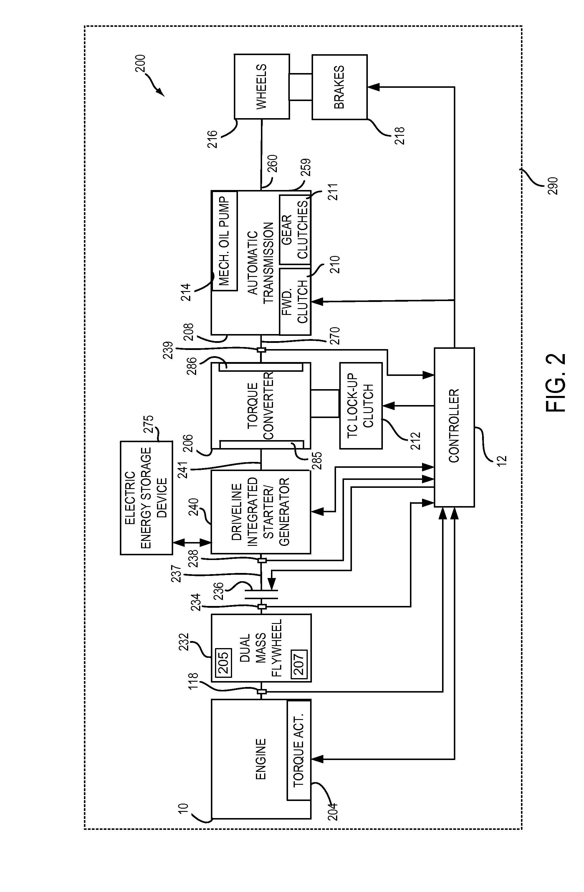
[0015]The present description is related to controlling driveline operation for a hybrid vehicle. The hybrid vehicle may include an engine and a driveline integrated starter / generator (DISG) or electric machine (e.g., motor / generator) as shown in FIGS. 1-2. The engine may be operated with or without the DISG during vehicle operation via a driveline disconnect clutch. The DISG is integrated into the driveline on the same axis as the engine crankshaft and rotates whenever a transmission torque converter impeller rotates. Further, the DISG may not be selectively engaged or disengaged from the driveline. Rather, the DISG is an integral part of the driveline. Further still, the DISG may be operated with or without operating the engine. The driveline may be operated as shown in the sequence of FIG. 3 according to the method of FIG. 4. Finally, FIG. 5 shows an example offset position between two position identifying devices.

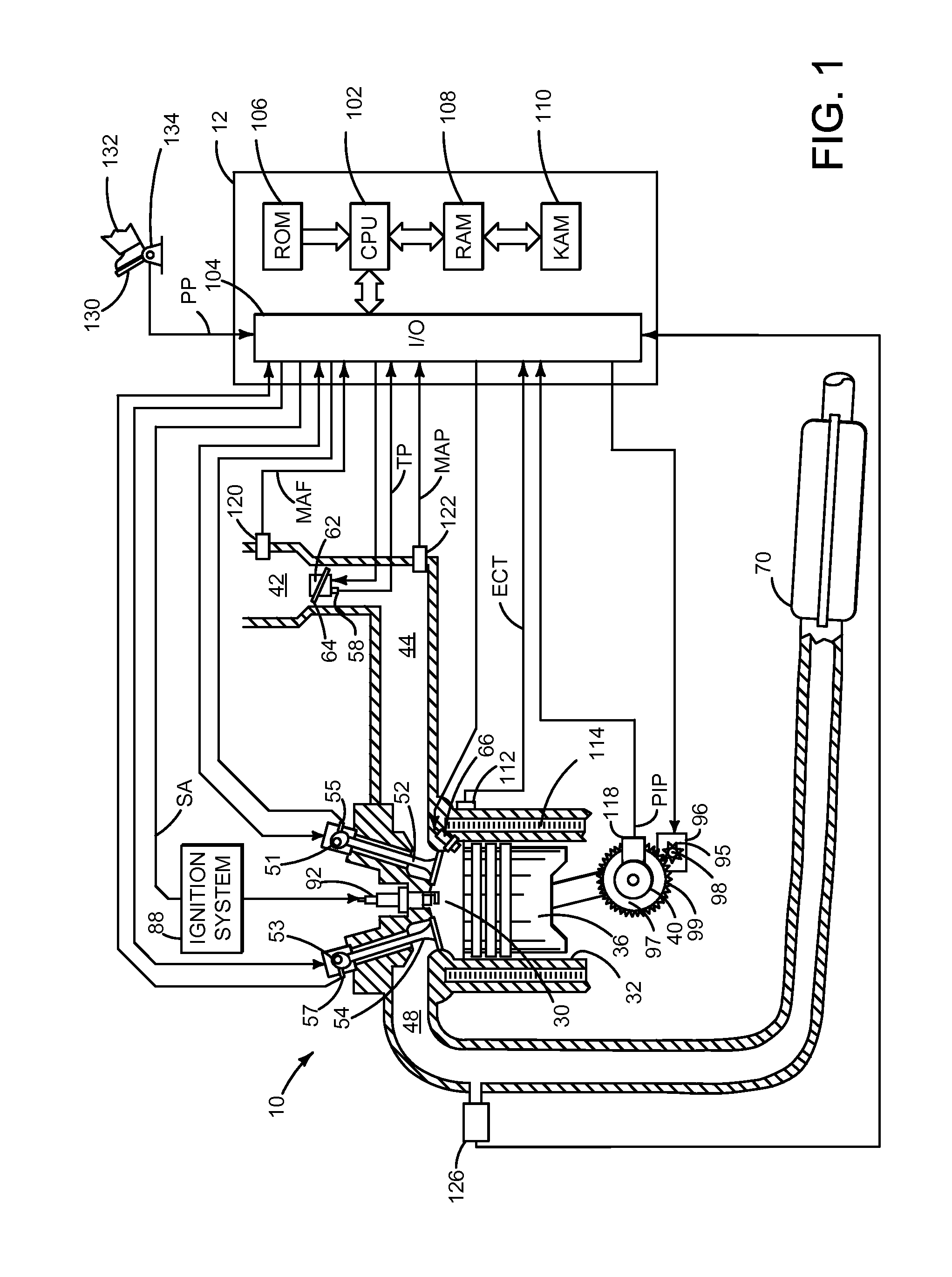
[0016]Referring to FIG. 1, internal combustion engine 10, comprisi...


PUM


Abstract

Systems and methods for improving hybrid vehicle torque control are presented. The system and methods included may estimate driveline torque via springs of a dual mass flywheel. The estimated driveline torque may provide feedback for adjusting operation of a driveline disconnect clutch and / or engine torque.

Description

FIELD[0001]The present description relates to a system and methods for estimating driveline torque and using the driveline torque estimate to operate a vehicle. The methods may be particularly useful for hybrid vehicles that include a driveline with a disconnect clutch.BACKGROUND AND SUMMARY[0002]A hybrid vehicle driveline may include a driveline disconnect clutch. The driveline disconnect clutch may be selectively engaged to couple an engine to a motor and other driveline components. The driveline disconnect clutch may be opened during periods of low driver demand torque so that engine rotation may stop while the motor provides torque to control vehicle motion. At times of higher driver demand torque, the driveline disconnect clutch may be closed so that engine torque may be added to motor torque to provide a desired driver demand torque. However, it may be challenging to provide an accurate estimate of driveline torque produced by the engine to meet the driver demand torque.[0003]...

Claims


Application Information

Patent Timeline
Patent Type & Authority Applications(United States)
IPC IPC(8): B60W20/00B60W10/02
CPCB60W20/10Y10S903/902B60W10/02B60W10/06B60W20/00B60W2510/1025B60W2710/0666B60W2422/40B60Y2400/48F16F15/131
Inventor GIBSON, ALEX O`CONNORDOERING, JEFFREY ALLENLEE, SEUNG-HOONFUJII, YUJIMCCALLUM, JAMES WILLIAM LOCHGOODWIN, WILLIAM RUSSELL
Owner FORD GLOBAL TECH LLC
Why Eureka
Try Eureka