
Double baffle vascular occluder

Active Publication Date: 2015-02-19
COOK MEDICAL TECH LLC
View PDF14 Cites 3 Cited by
  • Summary
  • Abstract
  • Description
  • Claims
  • Application Information

AI Technical Summary

Benefits of technology

The patent describes a device that can be left in a patient's body to prevent blood flow through a specific vessel. The device has a chamber that can hold a thrombogenic agent to help cause clotting. The device is designed to be stable and secure in the patient's body, minimizing the risk of complications like migration or deformation. The device can be expanded within the patient's vessel to ensure a proper fit and optimal function. The patent also describes the use of a membrane that can allow blood to pass through and clot within the device, creating an additional barrier to blood flow. The patent also mentions the use of a stent ring as an expansion device for the device. Overall, the patent provides a solution for creating a reliable and effective occluder for use in various medical procedures.

Problems solved by technology

This required an open surgery procedure with consequential risks and complications.
In this regard, it can take time to attain adequate occlusion and also the length of the occluding barrier, that is the overall length of the implanted coils, will vary and can be significant.
In some cases, there may not be sufficient room in a vessel to accommodate a long length of coils without adversely affecting other parts of the patient's vasculature, such as side branches bifurcations and so on.
However, occlusions of this nature can be liable to recanalization; that is, to leakage through the occluding barrier and reopening of the vessel.
Other types of implantable occluders seek to mitigate the above drawbacks but can still be prone to migration, recanalization and migration following implantation.

Method used


Image

  • Double baffle vascular occluder
  • Double baffle vascular occluder
  • Double baffle vascular occluder

Examples


Embodiment Construction

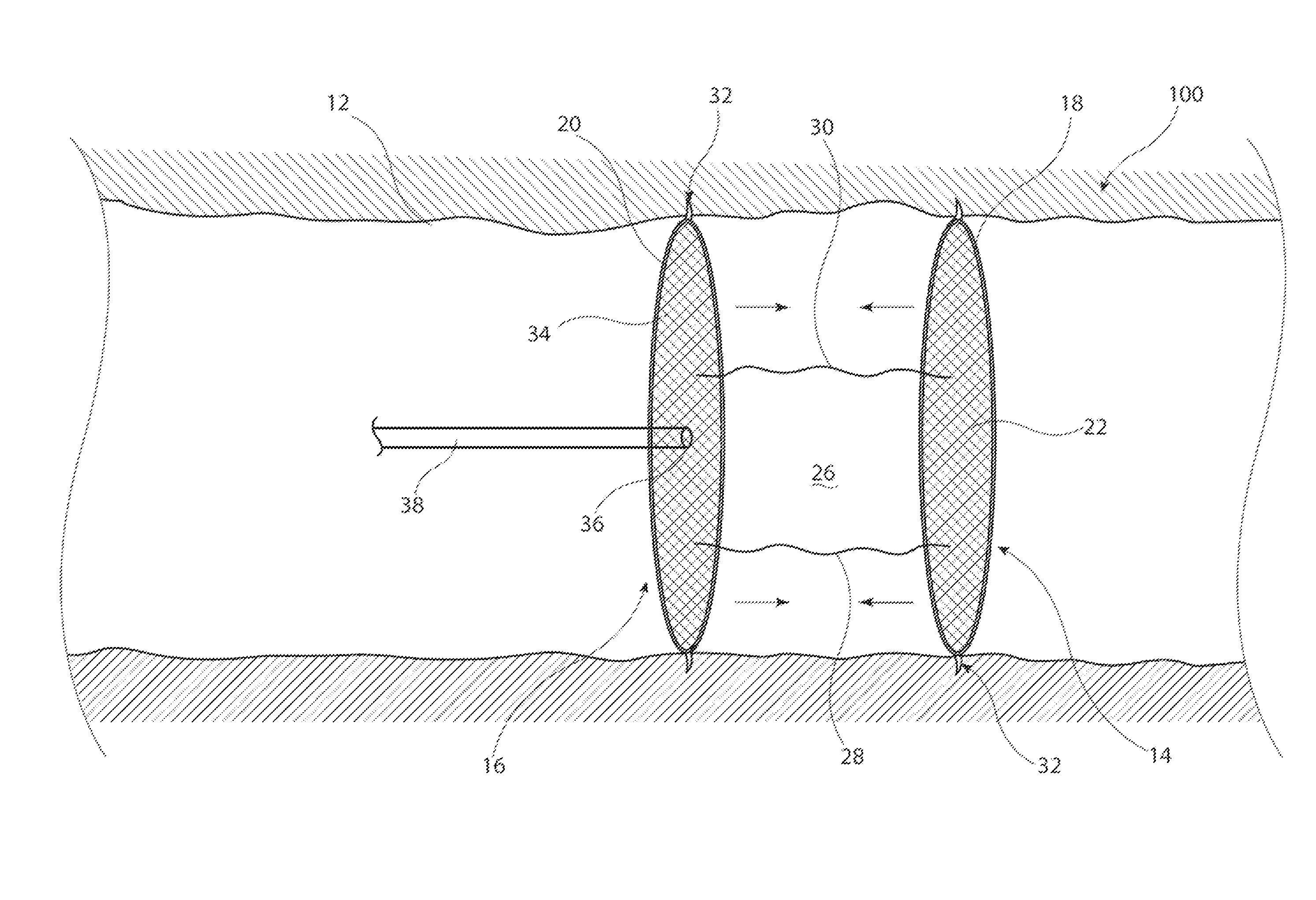
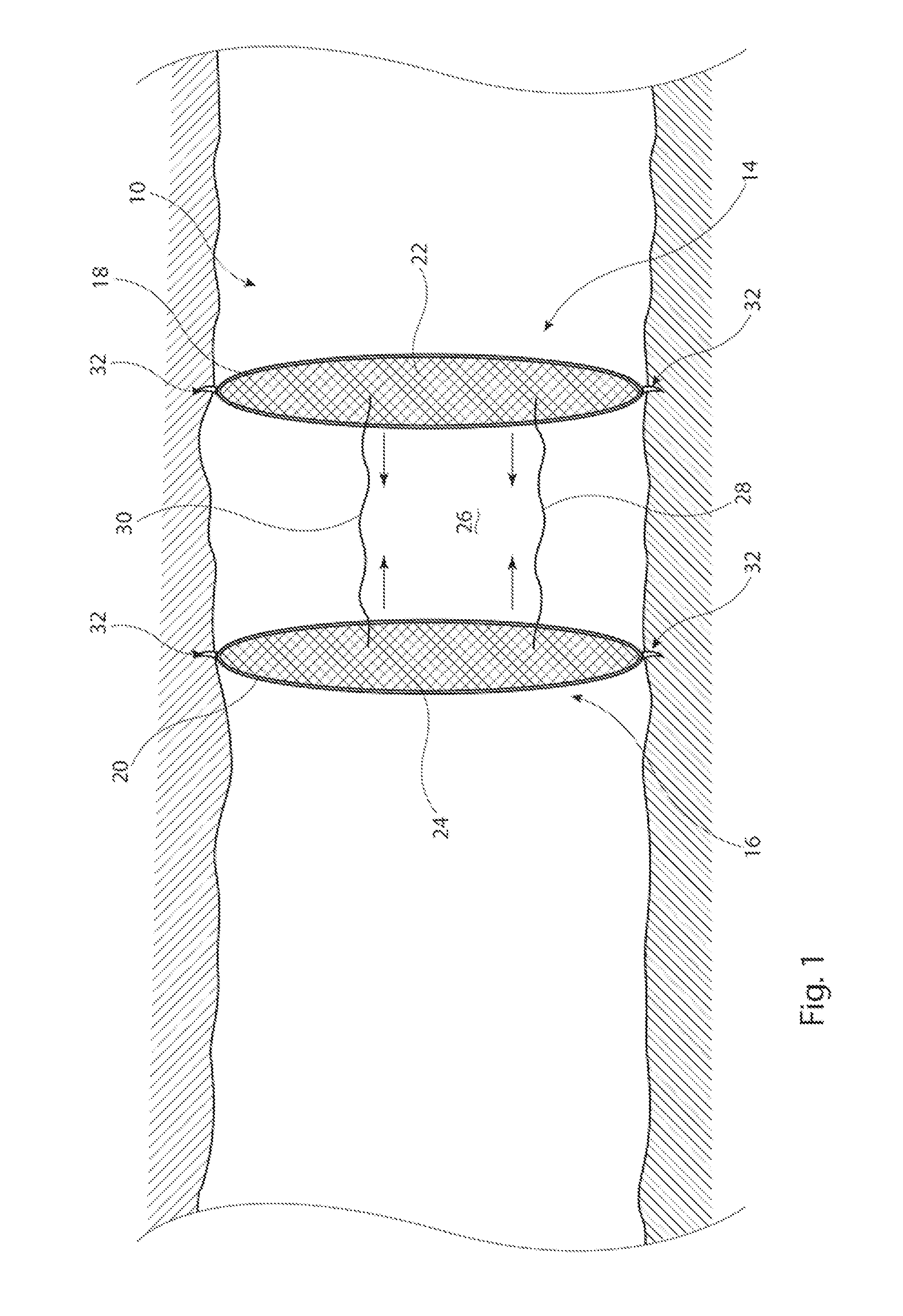
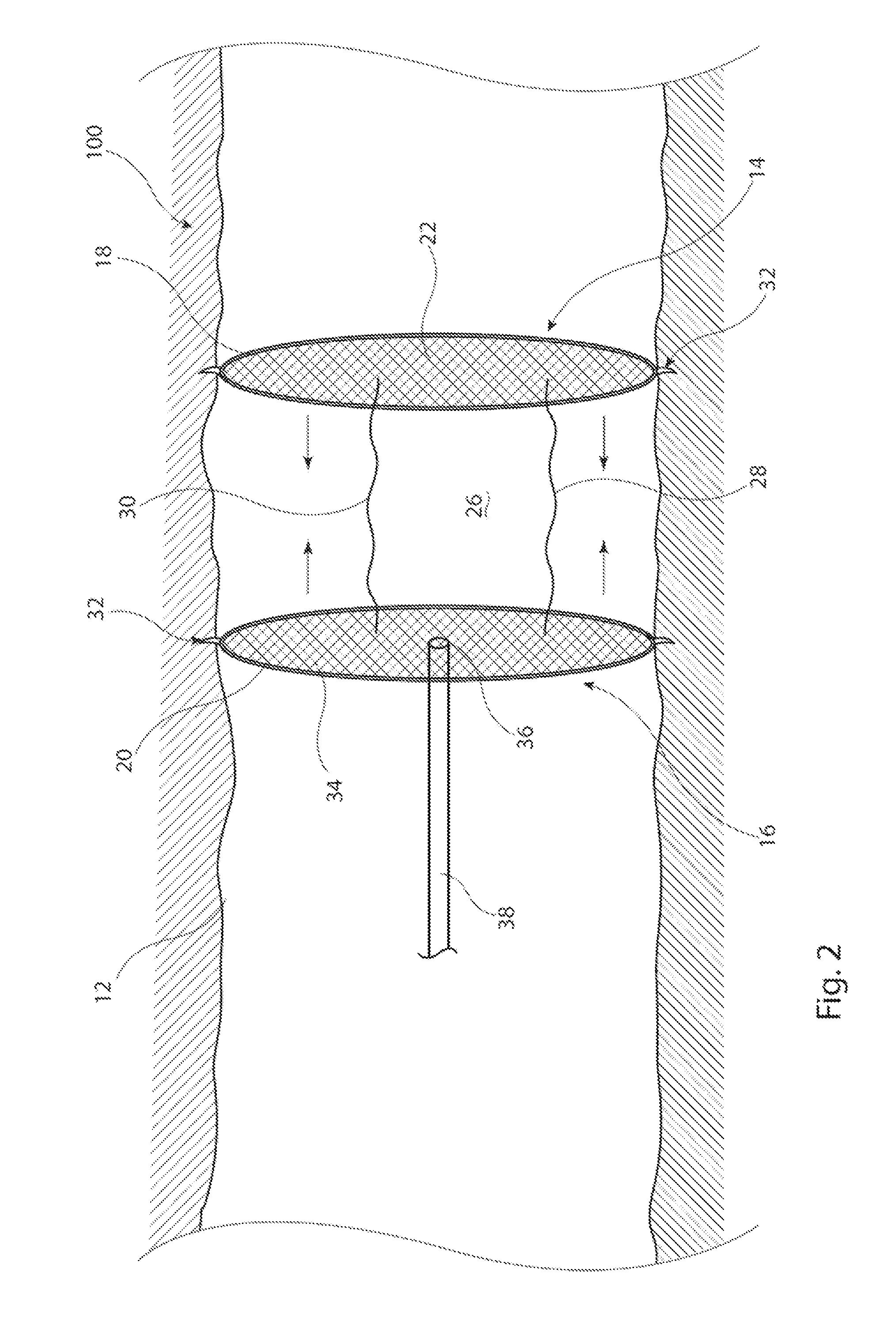
[0031]Described below are various embodiments of a vascular occluder for deployment in a patient or animal in order to occlude a body vessel. The structures taught herein are suitable for occluding a wide variety of blood vessels, both of large as well as of small diameter. They are also suitable in high pressure vessels.

[0032]The embodiments of occluder described herein include first and second baffle members which in the preferred embodiment have a substantially disk-shaped form and which are coupled to one another by a plurality of spacer elements, which hold the baffle members in position and provide a chamber between the baffle members in which blood therein can clot as a result of blood statis and / or agent activated thrombosis.

[0033]It is to be understood that the drawings are schematic only and not to scale. Nevertheless, the skilled person will appreciate the technical elements depicted in the drawings and that these form an integral part of the disclosure of this patent spe...


PUM


Abstract

A vascular occluder includes first and second baffle members which are formed of an expansion device such as a stent across which extends an impermeable membrane. The baffle members are held at a given separation by spacer elements. The separation creates a chamber between the baffle members in which the blood is able to stagnate, thereby creating a second occlusion barrier. One of the baffle members may have an aperture within its membrane for receiving a delivery catheter for delivery of thrombogenic agent into the chamber. The occluder has a given length, thereby making it suitable for implantation in difficult vessel sections and is also able to avoid problems of recanalization of the vessel which can occur with prior art occluders.

Description

CROSS REFERENCE TO RELATED APPLICATIONS[0001]This application is related to and claims the benefit of priority to British patent application number GB 1314486.0, filed Aug. 13, 2013, which is incorporated herein by reference in its entirety.TECHNICAL FIELD[0002]The present invention relates to a vascular occluder for implantation into a vessel of a human or animal.BACKGROUND ART[0003]There are several medical indications for which vascular occlusion is an appropriate treatment including, for example, for rerouting blood to a different part of a patient's body, to reduce or halt supply of blood to a tumor or other growth, to reduce the supply of blood to an organ or area of a patient's body prior to a medical procedure or treatment, to reduce pressure on a fistula, weakened or leaking blood vessel, and so on.[0004]Conventionally, vascular occlusion was effected by surgically closing, or ligating, the blood vessel. This required an open surgery procedure with consequential risks and c...

Claims


Application Information

Patent Timeline
IPC IPC(8): A61B17/12
CPCA61B17/12109A61B2017/1205A61B17/12172A61B17/12177A61B17/12031A61B17/12045A61B17/12168
Inventor CONDER, ANDREW W.MARKER, DAVID NOWAKLEBLANC, JOHN R.SAHLGREN, SUSAN GALLHERDAHL, CASPER
Owner COOK MEDICAL TECH LLC
Learn More