Devices and Methods for Inserting a Vertebral Fixation Member

a technology of fixation member and device, which is applied in the field of devices and methods for inserting vertebral fixation members, can solve the problems of increasing the potential for non-ideal rod placement, limited access locations for rods, and incisions that are added or elongated

Active Publication Date: 2015-02-19
GLOBUS MEDICAL INC
View PDF26 Cites 22 Cited by
  • Summary
  • Abstract
  • Description
  • Claims
  • Application Information

AI Technical Summary

Benefits of technology

[0012]The stabilization member insertion device releasably and rotatably links to the elongate stabilization member. The stabilization member insertion device is configured and dimensioned to be received within the open central portion such that the insertion device is moveable along the central longitudinal axis. The elongate stabilization member may be cantilevered off the stabilization member insertion device such that at least a portion of the elongate stabilization member is positioned outside the at least one extended tab. This configuration may allow for longer rods to be utilized.
[0013]The elongate stabilization member is deliverable in a first orientation substantially parallel to the central longitudinal axis of the open central portion; and, independent of movement along the central longitudinal axis, the elongate stabilization member is rotatably actuatable by the stabilization member insertion device to extend in a second orientation angled with respect to the first orientation to position the stabilization member in relation to the first anchor. The insertion and articulation of the elongate stabilization member may be controlled with the use of fluoroscopy, for example, to help guide axial and rotation movements.

Problems solved by technology

For minimally invasive surgical procedures, for example, there may be limited access locations for the rods.
In addition, many existing rod holders are fixed position with limited freedom of movement, which increases the potential for non-ideal rod placement.
This may result in additional or elongated incisions, excessive rod reduction, or complete removal of the rod and reinsertion increasing muscle and tissue damage.

Method used


Image

  • Devices and Methods for Inserting a Vertebral Fixation Member
  • Devices and Methods for Inserting a Vertebral Fixation Member
  • Devices and Methods for Inserting a Vertebral Fixation Member

Examples


Embodiment Construction

[0057]The various embodiments of the invention will now be described with reference to the attached drawing figures. The following detailed description of the invention is not intended to be illustrative of all embodiments. In describing the various embodiments of the present invention, specific terminology is employed for the sake of clarity. However, the invention is not intended to be limited to the specific terminology so selected. It is to be understood that each specific element includes all technical equivalents that operate in a similar manner to accomplish a similar purpose. The features of one embodiment may be employed with other embodiments as the skilled artisan would recognize, even if not explicitly stated herein.

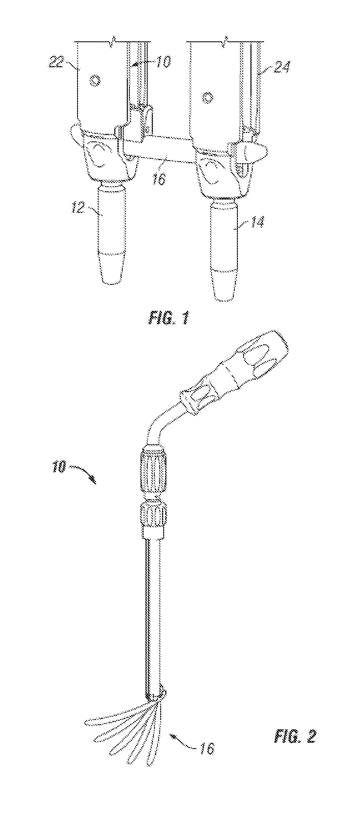
[0058]Referring to FIG. 1, one embodiment of a stabilization member insertion device 10 is shown positioned within one embodiment of a sleeve 22 that is mated to a first anchor 12. A second anchor 14 is shown attached to a second sleeve 24. A connecting membe...


PUM


Abstract

Devices, systems, and methods for inserting a vertebral stabilization member, such as a rod. The insertion device includes an outer guide tube, a pin assembly including a pin and a pusher member extending therethrough. The insertion device is configured to actuate a rod between a first orientation and a second orientation angled with respect to the first orientation in order to position the rod in an appropriate location for attachment to bone.

Description

CROSS REFERENCE TO RELATED APPLICATION[0001]The present application is a continuation-in-part of U.S. patent application Ser. No. 12 / 413,058 filed on Mar. 27, 2009, the entire disclosure of which is incorporated herein by reference in its entirety for all purposes.FIELD OF THE INVENTION[0002]The present invention relates generally to devices and methods for inserting a vertebral fixation member, and more particularly, but not exclusively, to rod insertion devices and methods.BACKGROUND OF THE INVENTION[0003]Many types of spinal irregularities can cause pain, limit range of motion, or injure the nervous system within the spinal column. These irregularities can result from, without limitation, trauma, tumor, disc degeneration, and disease. Often, these irregularities are treated by immobilizing a portion of the spine. This treatment typically involves affixing a plurality of screws and / or hooks to one or more vertebrae and connecting the screws or hooks to an elongate rod that general...

Claims


Application Information

Patent Timeline
Patent Type & Authority Applications(United States)
IPC IPC(8): A61B17/70
CPCA61B17/7085A61B17/0206A61B17/7004A61B17/708A61B17/7086
Inventor CRYDER, JOELBECHTEL, MATTHEWIOTT, ANDREWKARPOWICZ, EDWARDCAHILL, DOUGLASRIGHTLER, ROBERT
Owner GLOBUS MEDICAL INC
Why Eureka
Try Eureka