
Detecting method of abnormality of machine tool operation

a machine tool and abnormality technology, applied in the direction of computer control, program control, instruments, etc., can solve the problems of unable to apply the detection method to other tools without the chip, and not being able to detect other abnormalities

Inactive Publication Date: 2015-02-19
KOREA TOOL MONITORING
View PDF13 Cites 23 Cited by
  • Summary
  • Abstract
  • Description
  • Claims
  • Application Information

AI Technical Summary

Benefits of technology

The present invention provides a method for detecting abnormal machine tool operation with high accuracy, even when there are external vibrations or intermittent power supply instability. The method allows for the preset skipping of alarms to prevent false alarms, while also allowing for continuous monitoring of machine tool operation.

Problems solved by technology

However, the above-mentioned detecting method can be applied only to a tool with the chip but cannot be applied to other tools without the chip.
Further, it is not possible to detect other abnormal state, e.g., in case that the tool is erroneously installed on the machine tool.
However, these methods also have a problem in that it is not possible to detect other abnormal state, e.g., in case that the tool is erroneously installed.
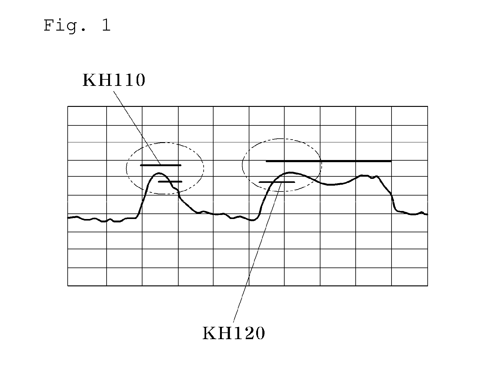
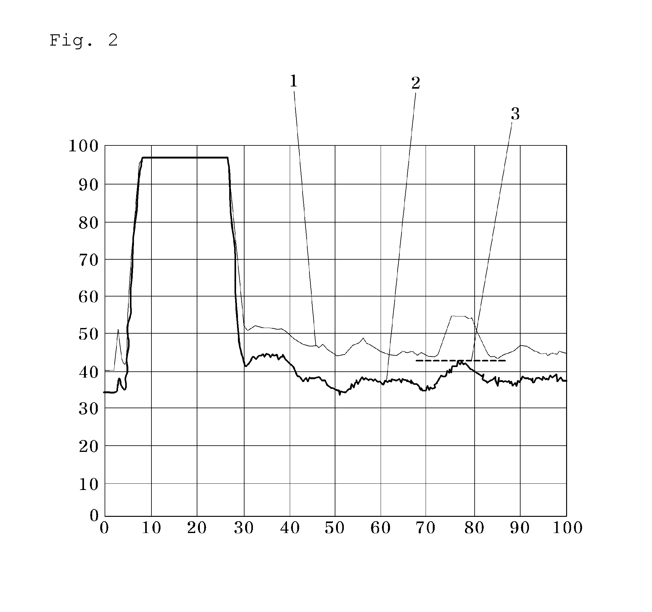
However, in the above-mentioned detecting method (tool monitoring system), when abnormality of a power supply system or shaking of a tool is occurred by external vibration or intermittent instability in power supply, a load (power) value of a motor is suddenly reduced or increased, as shown in FIG. 2.
As a result thereof, the alarm is erroneously operated, and thus the operator operates the machine tool while turning off the tool monitoring system, thereby deteriorating usefulness and reliability of the tool monitoring system.

Method used


Image

  • Detecting method of abnormality of machine tool operation
  • Detecting method of abnormality of machine tool operation
  • Detecting method of abnormality of machine tool operation

Examples


Embodiment Construction

[0029]

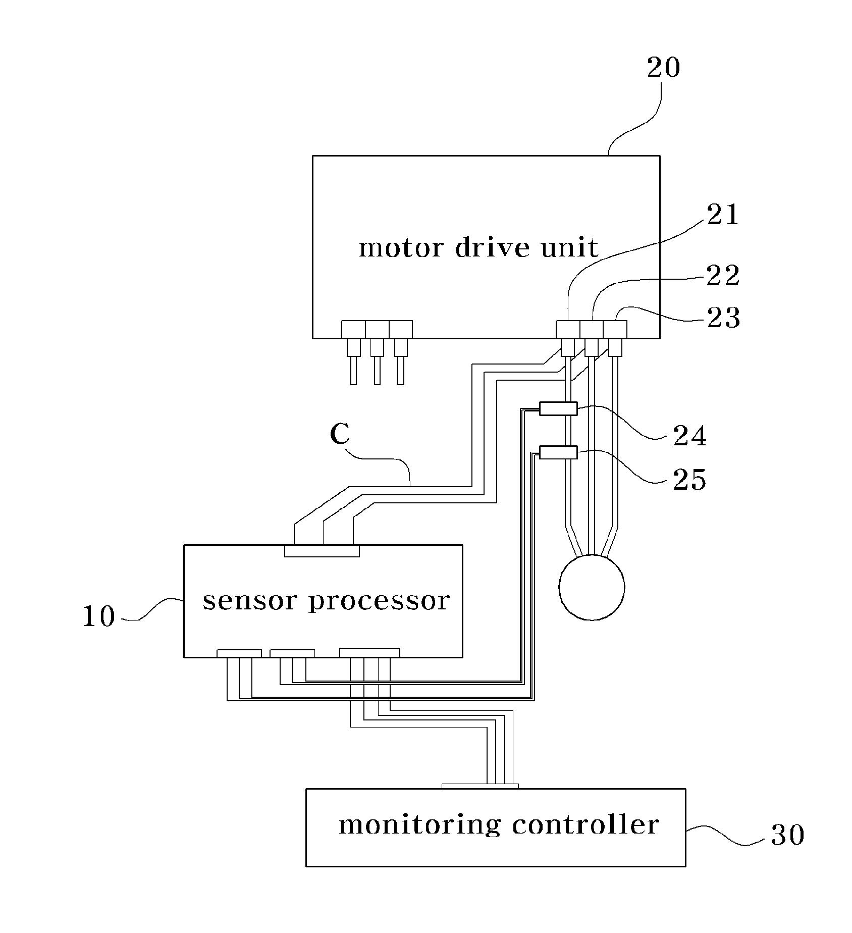
 1: reference waveform 2: machining waveform3: essential passage line10: sensor processor20: motor drive unit21, 22, 23: servo axis terminal24: current sensor25: voltage sensor30: monitoring controller40: host computer50: machine tool controllerC: communication cable

Description of Specific Embodiments

[0030]The advantages, features and aspects of the invention will become apparent from the following description of the embodiments with reference to the accompanying drawings, which is set forth hereinafter.

[0031]The present invention is to provide a detecting method of abnormality of a machine tool operation, which can precisely detect the abnormality of the machine tool operation, such as the chucking miss of a material, and the wear and damage state of a tool. To this end, as shown in FIG. 3, the present invention includes a preparing step S100, a reference waveform obtaining step S200, a monitoring section setting step S300, a permissible limit setting step S400 and a monitori...


PUM


Abstract

Provided is a detecting method of abnormality of a machine tool operation, and the detecting method includes a preparing step S100; a reference waveform obtaining step S200 of measuring a drive voltage and a drive current, while machining the material in a normal state of the machine tool, and obtaining a reference waveform; a monitoring section setting step S300 of setting a monitoring section and thus automatically calculating a maximum load value and a minimum load value; a permissible limit setting step S400 of setting maximum and minimum permissible limits; and a monitoring step S500 of obtaining a machining load generated and determining whether a difference between maximum and minimum load values of the machining load is out of the maximum or minimum permissive limit and then outputting normality or abnormality thereof.

Description

CROSS-REFERENCE(S) TO RELATED APPLICATIONS[0001]The present invention claims priority of Korean Patent Application No. 10-2013-0096931, filed on Aug. 14, 2013, which is incorporated herein by reference.BACKGROUND OF THE INVENTION[0002]1. Field of the Invention[0003]The present invention relates to a detecting method of abnormality of a machine tool operation, and more particularly to a detecting method of abnormality of a machine tool operation, which can efficiently detect the wear state of a tool and the abnormal state between a tool and a material occurred upon the operation of a machine tool having a numeric control function.[0004]2. Description of Related Art[0005]Recently, with the development of electronic technology, various machine tools having high accuracy and a numerical control function have been developed and used, and when machining a material using the machine tools, the degree of machining accuracy is typically changed depending on the wear state of a tool, the cont...

Claims


Application Information

Patent Timeline
IPC IPC(8): G05B19/4065
CPCG05B19/4065G05B19/4061G05B2219/37623G05B2219/50197B23Q17/09B23Q17/0985G05B2219/33098
Inventor KIM, BYUNG-HAKKIM, JONG-KOOK
Owner KOREA TOOL MONITORING
Learn More