Method for manufacturing composite double-metal fracture splitting connecting rod

Inactive Publication Date: 2015-02-26
JIANGSU UNIV
View PDF12 Cites 5 Cited by
  • Summary
  • Abstract
  • Description
  • Claims
  • Application Information

AI Technical Summary

Benefits of technology

[0028]1. The present invention provides a new approach of manufacturing fracture splitting connecting rods. The selection range of material for fracture splitting connecting rods is expanded, and aluminum alloy, titanium alloy, 40Cr and other materials may be utilized to manufacture fracture splitting connecting rods; and the application of the connecting rod fracture splitting technology is boosted;
[0029]2. The double-metal fracture splitting connecting rod integrates the advantages of two types of material, thereby ensuring the performance of the main body of the connecting rod and meeting the requirements of fracture splitting division of the large end portion of the connecting rod.
[0030]3. Compared with the conventionally common methods for manufacturing connecting rods by mechanically sawing and grinding a bonding surface, the present invention simplifies the machining procedures of connecting rods, reduces investments of fine-finishing equipments an

Problems solved by technology

A technical problem to be solved by the present invention is that the material for a fracture

Method used


Image

  • Method for manufacturing composite double-metal fracture splitting connecting rod
  • Method for manufacturing composite double-metal fracture splitting connecting rod
  • Method for manufacturing composite double-metal fracture splitting connecting rod

Examples


Example

[0036]In the figures: 1—Connecting rod body; 2—Fracture splitting interface; 3—Connecting rod cap; 4—Connecting bolt; 5—Fracture splitting layer; 6—Second casting system; 7—Separating plate; 8—First casting system; 9—Fracture splitting notch; and, 30—Jagged spacer.

DETAILED DESCRIPTION OF THE INVENTION

[0037]The present invention will be further described as below with reference to accompanying drawings by embodiments.

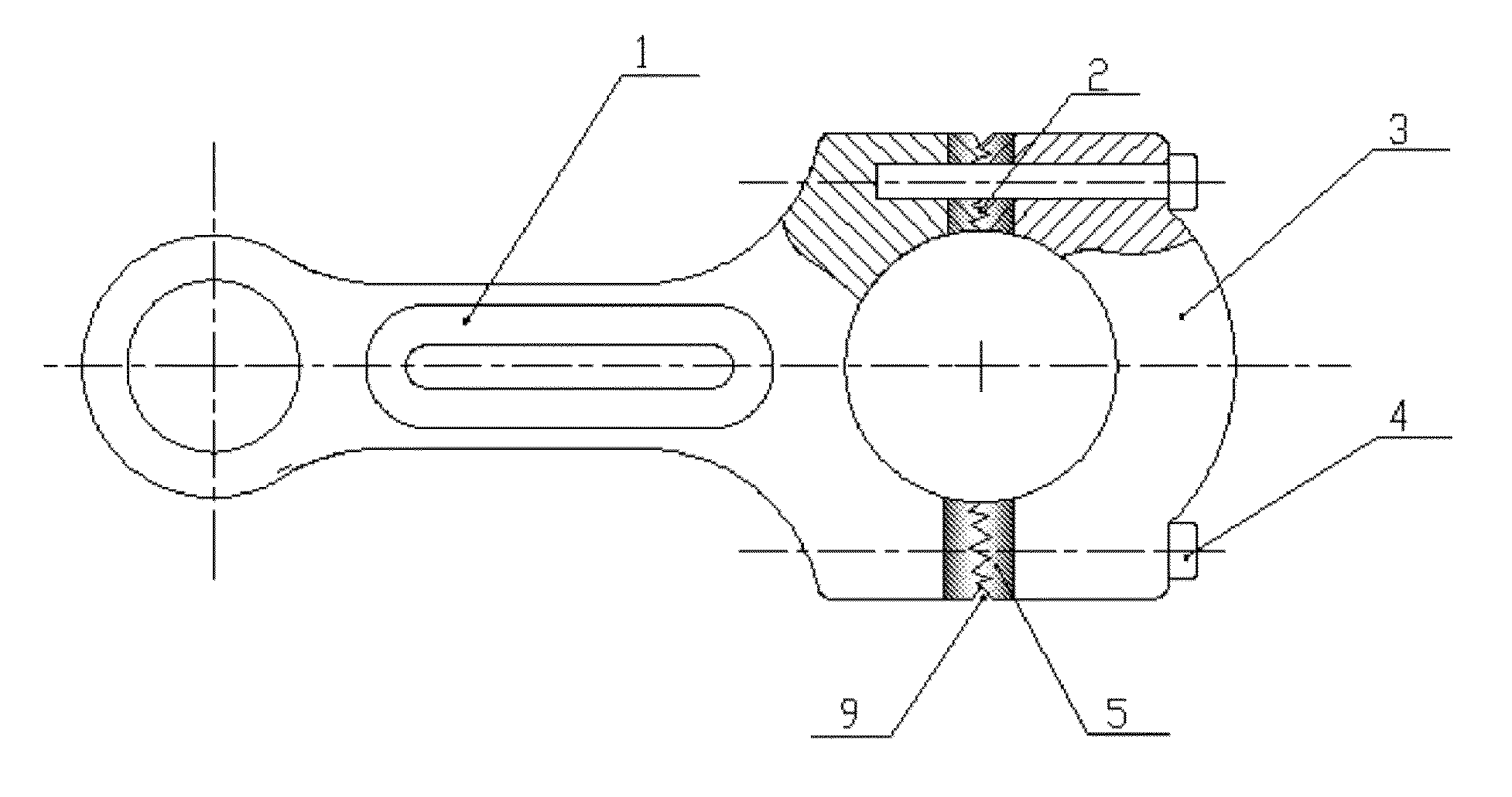
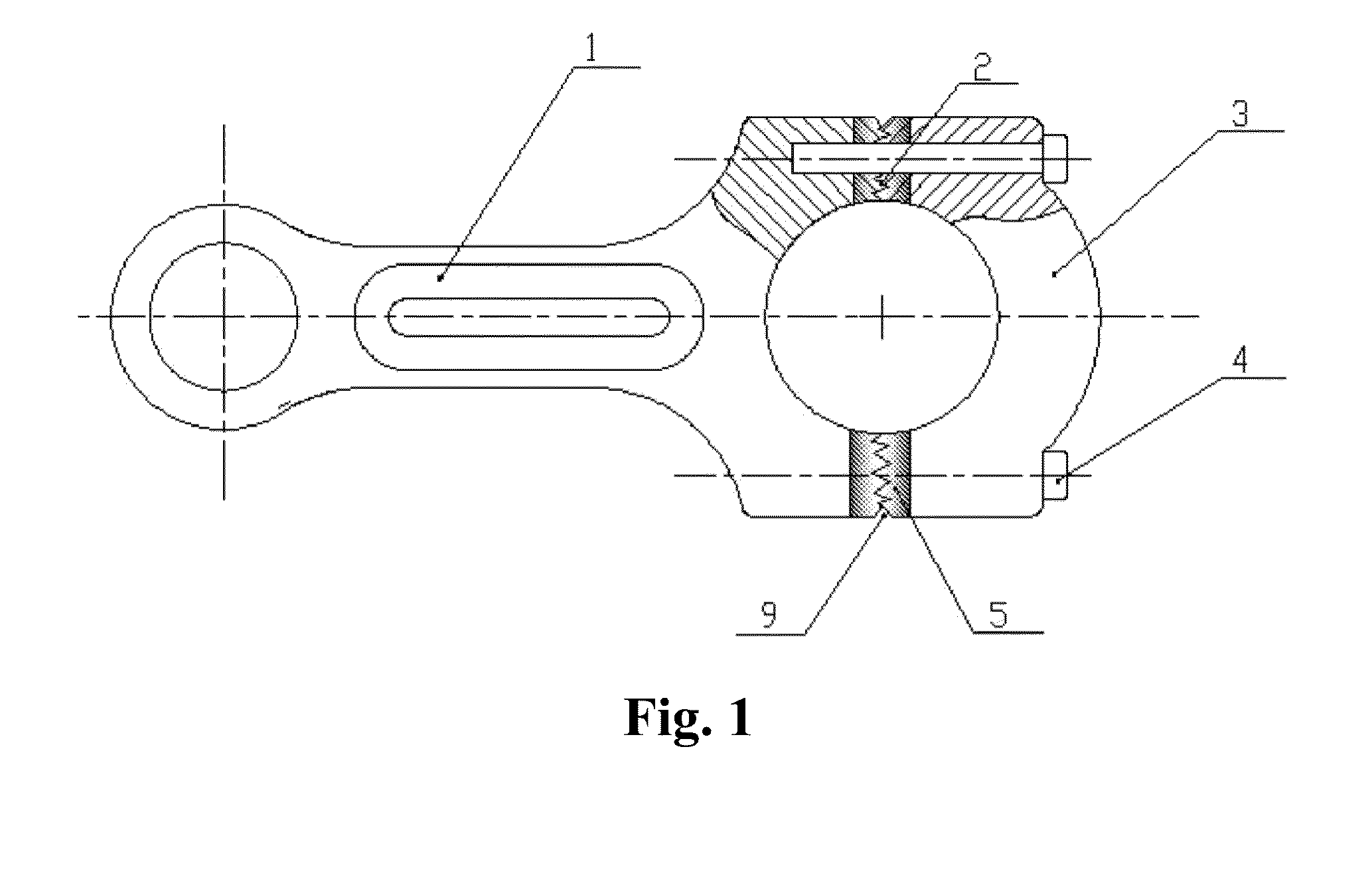
[0038]As shown in FIG. 1, a connecting rod in this embodiment consists of a connecting rod body 1 and a connecting rod cap 3, which are positioned and engaged by staggered structures on fracture splitting interfaces 2. The connecting rod body 1 and the connecting rod cap 3 are integrally connected by bolts 4.

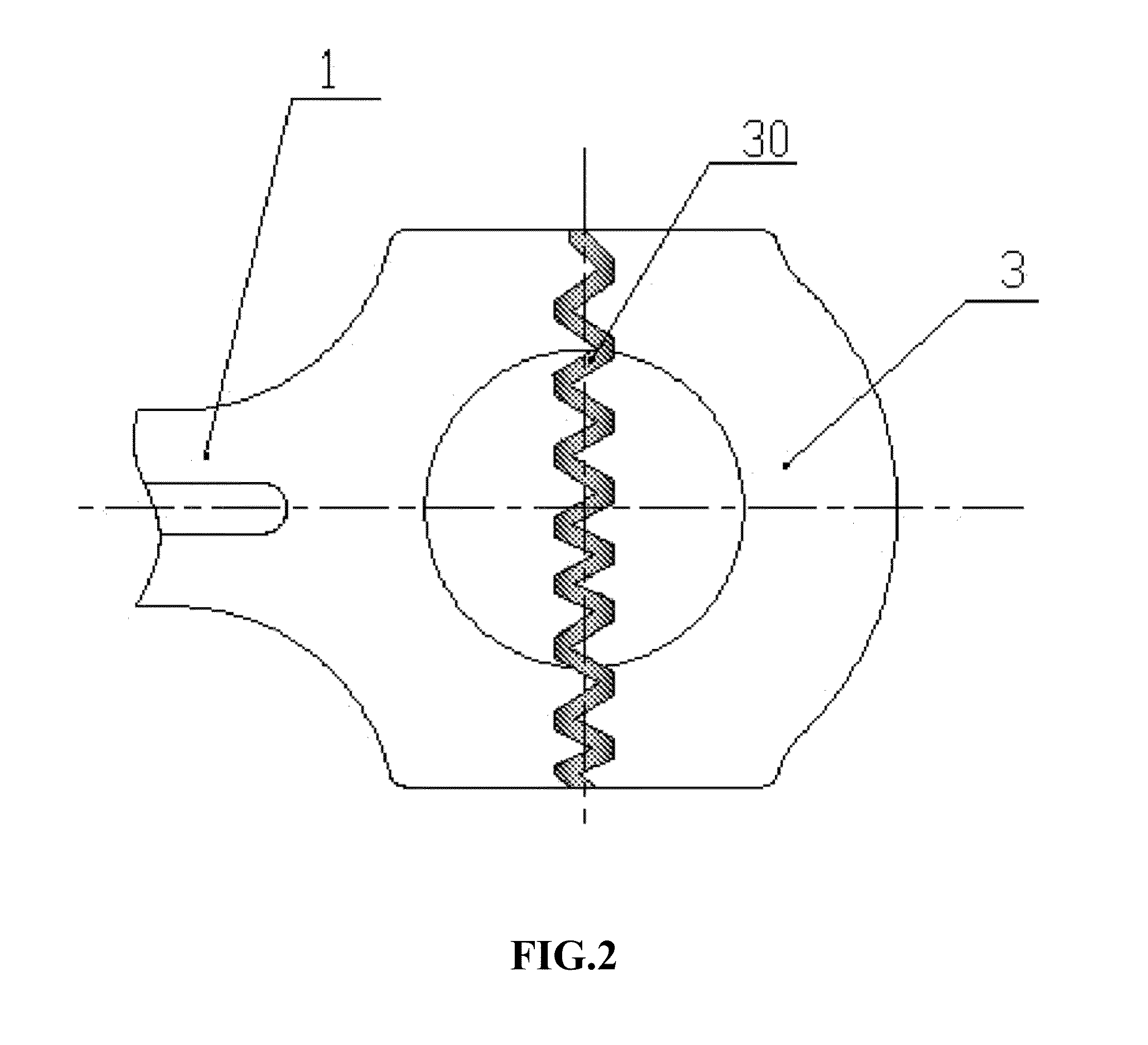
[0039]As shown in FIG. 1 and FIG. 3, the present invention employs the following technical solution. When a blank of a fracture splitting connecting rod is to be manufactured, a fracture splitting layer 5 is formed in a fracture splitting region and filled with mater...


PUM

PropertyMeasurementUnit
Thicknessaaaaaaaaaa
Pressureaaaaaaaaaa
Gravityaaaaaaaaaa

Abstract

The present invention provides a method for manufacturing a composite double-metal fracture splitting connecting rod, comprising the steps of: providing a moveable spacer at a large end of a mold cavity of a connecting rod, to divide the mold cavity into two separate parts; casting a connecting rod body and a connecting rod cap with material for the main body of the connecting rod; removing the spacer from the mold cavity when the majority of the material is solidified, then injecting material for a fracture splitting region into an empty mold cavity obtained after the removal of the spacer, and metallurgically bonding the two types of material to form a composite double-metal casting; then, separating the connecting rod body from the connecting rod cap by a fracture splitting apparatus along preset fracture surfaces; and positioning and accurately assembling through engaged staggered structures on the two fracture surfaces.

Description

TECHNICAL FIELD[0001]The present invention relates to a method for manufacturing a composite double-metal fracture splitting connecting rod, belonging to the manufacturing field of engine parts.BACKGROUND OF THE INVENTION[0002]As one of key parts of engines, connecting rods during their operating processes mainly bear tension, compression, bending and other high frequency alternating loads resulted from combustion explosive force and reciprocating inertial force. Due to poor working conditions and complicated motion states, the service life of the connecting rods is affected by fatigue, abrasion, vibration and the like. Therefore, the connecting rods must have high enough strength, rigidity and comprehensive mechanical properties.[0003]Conventional connecting rods are machined separately. After a blank of a connecting rod is forged integrally, bonding surfaces of a connecting rod body and a connecting rod cap are machined by sawing, milling, grinding and other methods. After a posit...

Claims


Application Information

Patent Timeline
IPC IPC(8): F16C7/02B22D19/16B22D19/04B22D19/00
CPCF16C7/023B22D19/04B22D19/16B22D19/009B22D21/007C22C21/00C22C21/02C22C21/14C22C21/16C22C21/18F16C9/045F16C2204/20F16C2220/06F16C2240/60
Inventor JIANG, WENFANJIANG, YINFANG
Owner JIANGSU UNIV
Why Eureka
Try Eureka