Load bank providing constant power

a load bank and constant power technology, applied in the field of load bank system, can solve the problems of not providing a load bank that is able to adjust the resistive or inductive elements

Inactive Publication Date: 2015-02-26
EXPERIUM TECH
View PDF2 Cites 6 Cited by
  • Summary
  • Abstract
  • Description
  • Claims
  • Application Information

AI Technical Summary

Benefits of technology

[0006]Further embodiments of the load bank include a measurement system for measuring a voltage across the input terminals as well as the current through the resistive path and the current through the inductive path. Embodiments of

Problems solved by technology

While the prior load banks provide certain control over characteristics of electrical load provided by the load bank, they do not provide a load bank that is able to adjust

Method used


Image

  • Load bank providing constant power
  • Load bank providing constant power
  • Load bank providing constant power

Examples


Embodiment Construction

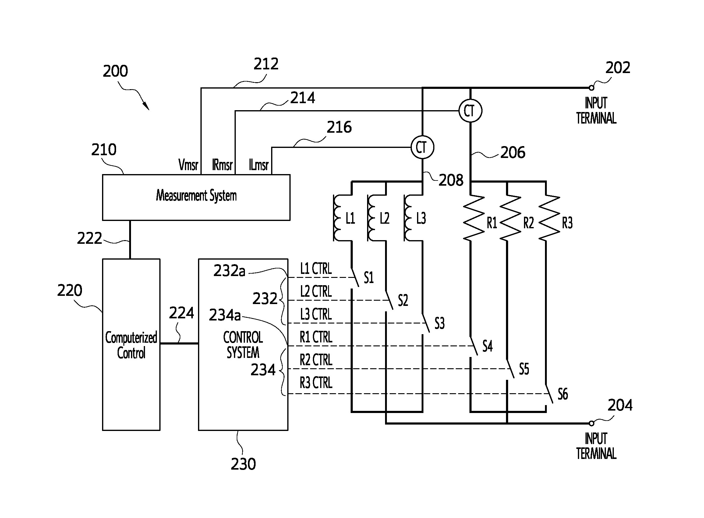
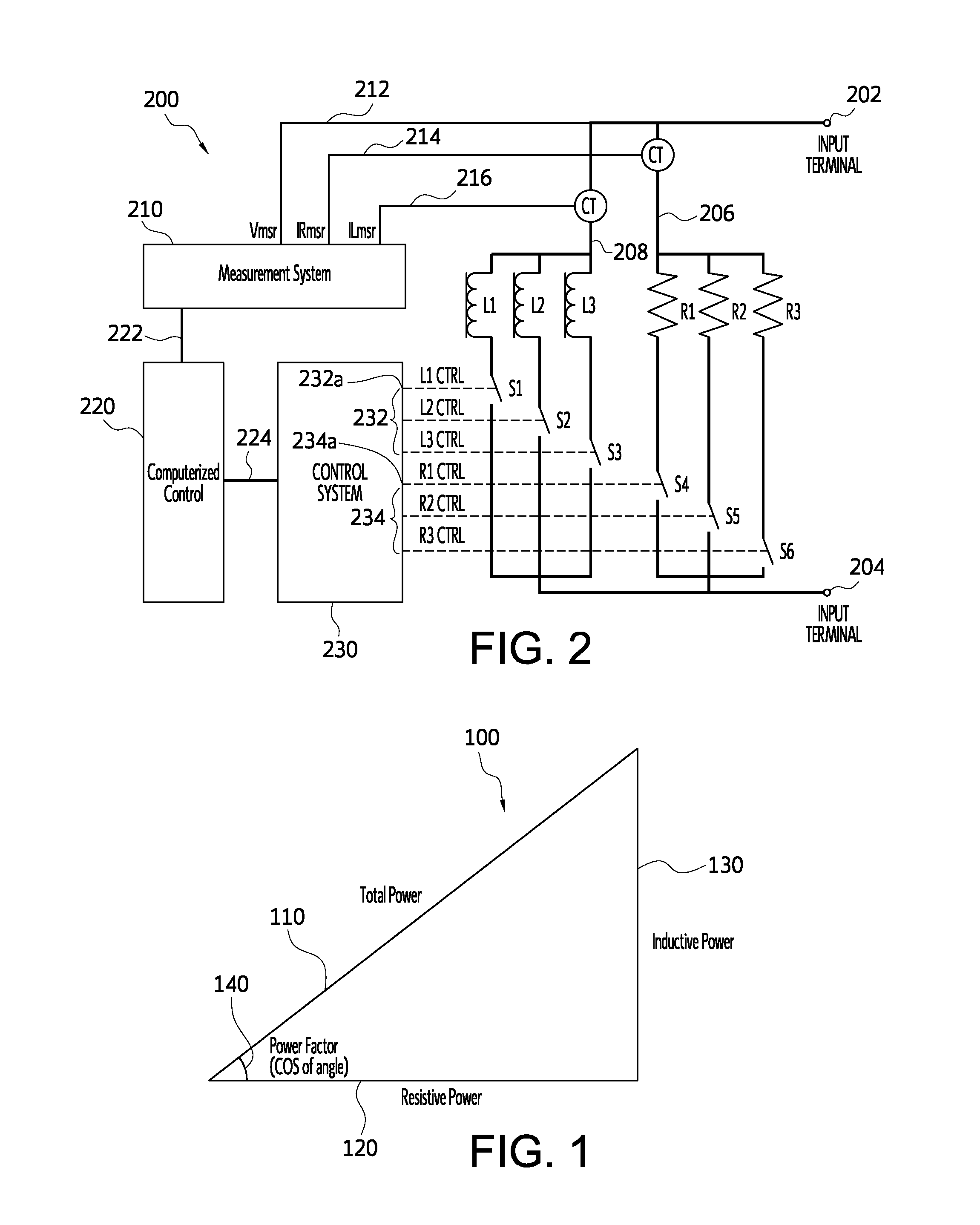
[0010]In an embodiment of the present invention, an adjustable load bank provides a load to a power source that is able to maintain constant power and constant current as well as power factor control. The load bank utilizes various resistive and inductive elements that may be connected or disconnected as required.

[0011]As shown in FIG. 1, the relationship among the total power (Ptotal), resistive power (Presist) and power (Pinduct) in an AC load bank can be understood with reference to a power triangle 100. In the power triangle, the length of the hypotenuse 110 represents the total power, also referred to as the apparent power, dissipated by a load bank applied to an AC power source. The base leg 120 represents the resistive power component of the load, which may be referred to as the real power. The vertical leg 130 represents the inductive power component, also referred to as the reactive power. Accordingly, the total power, measured in Volt-Amps (VA), may be determined by the fo...


PUM


Abstract

An adjustable load bank provides a load to a power source that is able to maintain a constant power and constant current as well as power factor control. The load bank utilizes various resistive and inductive elements that may be connected or disconnected as required. In operation, the load bank continuously monitors the voltage and current across the resistive and inductive elements and applies or subtracts elements as necessary via control signals in order to maintain the desired fixed total power dissipated by the load bank.

Description

BACKGROUND OF THE INVENTION[0001]A load bank system is often used to provide an electrical load for the testing of alternating current (“AC”) power sources such as power inverters and AC voltage generators. The load bank may include multiple resistive and / or inductive elements that can be individually connected in parallel to achieve a desired initial load.[0002]However, in various testing procedures it is often advantageous to maintain a constant power load on an electrical power source despite changes in the voltage applied to the load bank by the power source. Accordingly, there is a need for a load bank that is able to adjust the resistive or inductive elements that are connected in order to respond to changes in the applied voltage at the load bank's input terminals.BRIEF DESCRIPTION OF THE PRIOR ART[0003]Load bank systems are known in the prior art. For example, U.S. Pat. No. 5,424,588 to Cantor et al. discloses a load bank for use with DC power supplies that utilizes wire wou...

Claims


Application Information

Patent Timeline
IPC IPC(8): G05F1/12
CPCG05F1/12G05F1/70H02J3/1828Y02E40/30
Inventor PALATINI, LANCE
Owner EXPERIUM TECH
Why Eureka
Try Eureka