
Battery Energy Storage and Power System

a battery energy storage and power system technology, applied in the field of power systems, can solve the problems of shortening affecting the service life of batteries, and affecting the service life of batteries, and achieve the effect of stable voltag

Active Publication Date: 2015-02-26
ABB (SCHWEIZ) AG
View PDF12 Cites 17 Cited by
  • Summary
  • Abstract
  • Description
  • Claims
  • Application Information

AI Technical Summary

Benefits of technology

The patent is about using a controllable voltage source to protect battery energy storage from harmonic current (ripple) and ensure a stable voltage at the battery terminals. The technical effect is to enhance the stability and reliability of battery energy storage systems.

Problems solved by technology

The result can be unacceptable voltage amplitude variations, a voltage depression, or even a voltage collapse.
Such ripple may harm the batteries, by causing resistive heating and shortening their service life.
A disadvantage of such solution is that the DC / DC converter has to be rated for the full battery voltage, which may render the solution to be rather costly, in particular for high voltage STATCOM / BESS devices.

Method used


Image

  • Battery Energy Storage and Power System
  • Battery Energy Storage and Power System
  • Battery Energy Storage and Power System

Examples


Embodiment Construction

[0027]In the following description, for purposes of explanation and not limitation, specific details are set forth such as particular architectures, interfaces, techniques, etc. in order to provide a thorough understanding. In other instances, detailed descriptions of well-known devices, circuits, and methods are omitted so as not to obscure the description with unnecessary detail. Same reference numerals refer to same or similar elements throughout the description.

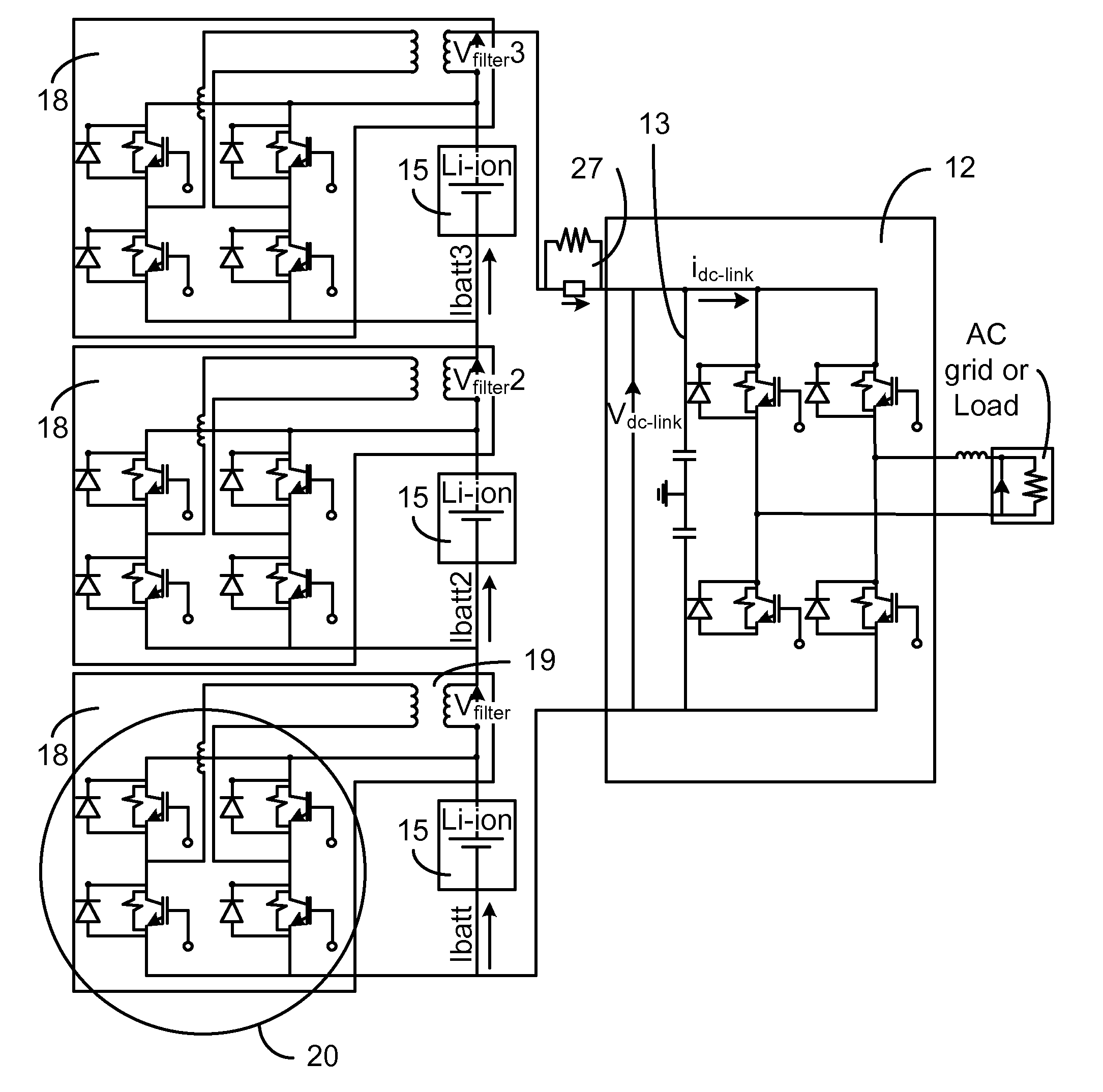
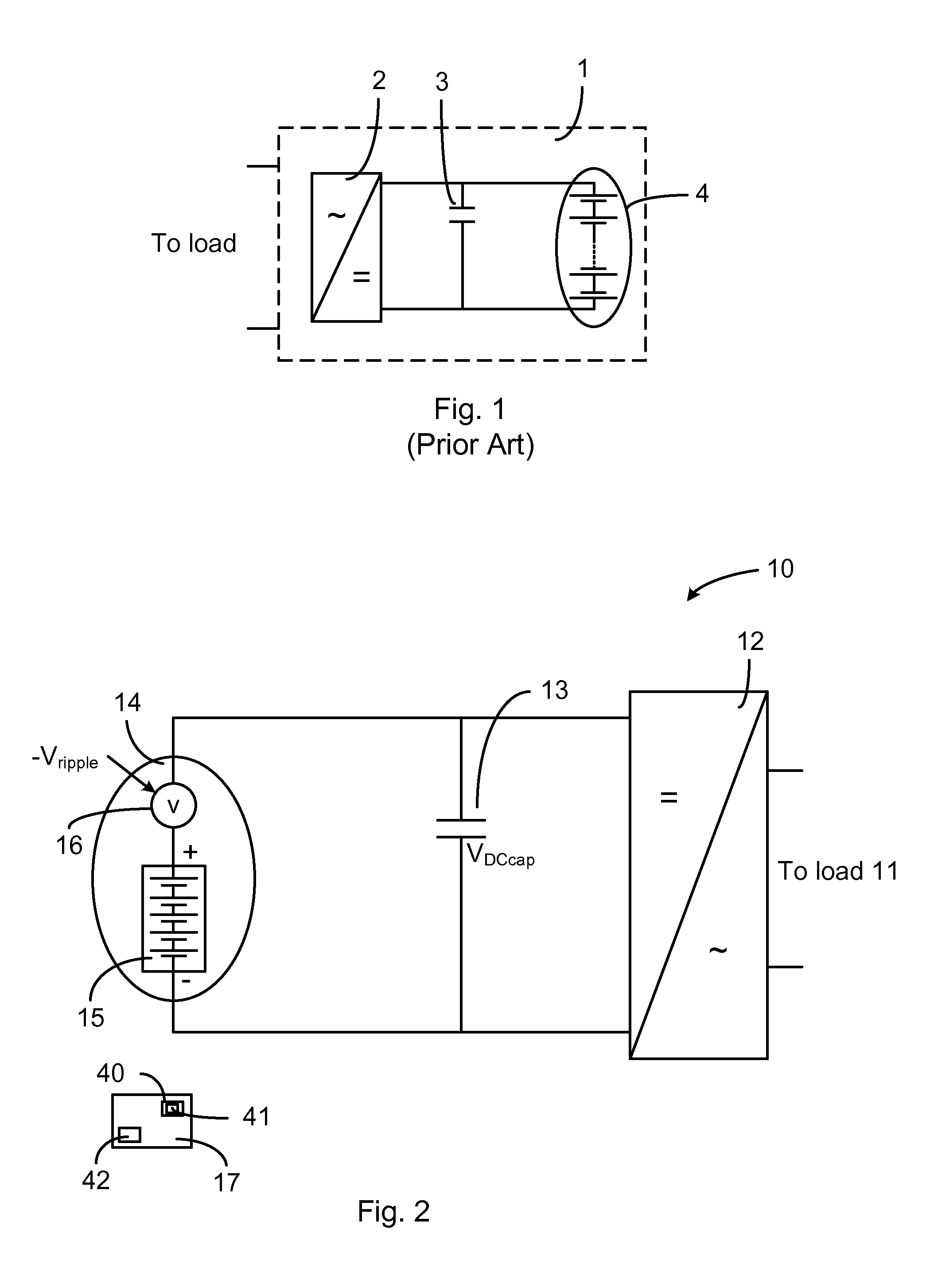
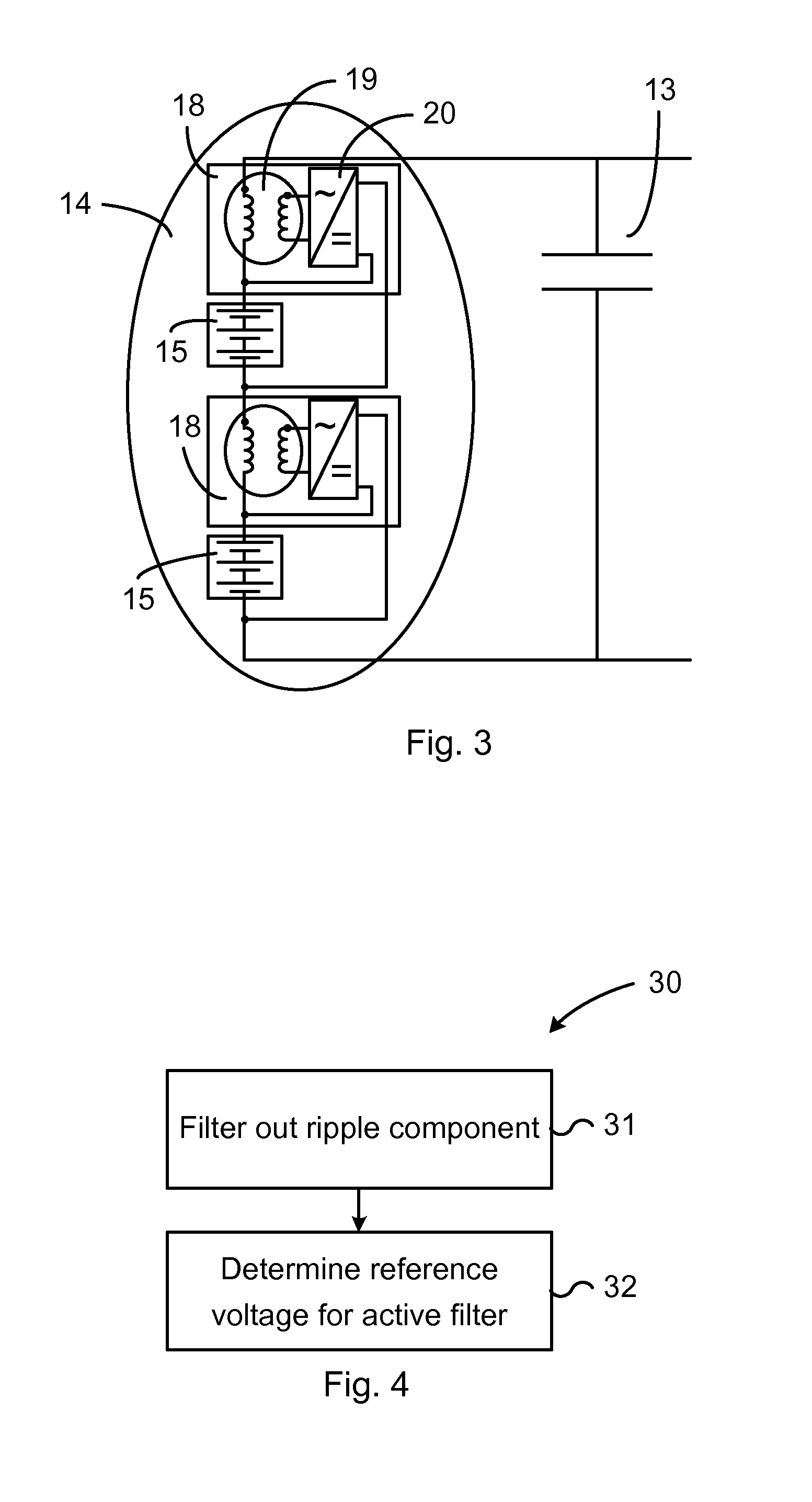
[0028]FIG. 2 illustrates an environment in which aspects of the present disclosure may be implemented. In particular, FIG. 2 illustrates a power system 10 that is suitable for connection to an alternating current load 11. The power system 10 comprises a power converter 12, for example a single-phase power converter or a single phase converter module, that comprises means for being connected to the load 11. The power converter 12 is in the following also denoted main converter. The load 11 may for example be an AC power gr...


PUM


Abstract

Battery energy storage arranged to be connected to a direct current capacitor, which is connected in parallel to a power converter. The battery energy storage includes a battery module and a controllable voltage source adapted to inject a voltage opposite to a voltage ripple of the direct current capacitor. A power system including such battery energy storage and a direct current capacitor is also disclosed.

Description

FIELD OF THE INVENTION[0001]The technology disclosed herein relates generally to the field of power systems, and in particular to battery energy storages and power systems comprising such battery energy storages.BACKGROUND OF THE INVENTION[0002]Electric power systems of different types, e.g. electric power transmission systems or railway systems, need to provide electric power in a reliable fashion. Therefore such systems may comprise energy storage devices, for example in form of direct current (DC) power sources. The energy storage devices may provide power for evening out fluctuations, shortages, etc. In for example the electric power transmission system, the load varies considerably during, e.g. day and night, i.e. the active power balance and the reactive power balance in the system thus also varies. The result can be unacceptable voltage amplitude variations, a voltage depression, or even a voltage collapse.[0003]A reactive power compensator may be provided with an energy stor...

Claims


Application Information

Patent Timeline
IPC IPC(8): H02M7/5387H02M1/12H02M1/14H02M1/00
CPCH02M7/5387H02M1/12H02M1/14H02J3/28H02J3/32H02M1/15H01M16/003Y02E60/50Y02E40/10H02M1/143H02M1/0093
Inventor TENGNER, TOMASALVES, ROBERTO
Owner ABB (SCHWEIZ) AG
Learn More