Acoustic source separation

a technology of acoustic source and acoustic source, which is applied in the direction of loudspeakers, microphone structural associations, mouthpiece/microphone attachments, etc., can solve the problems of inability to easily manufacture using the production techniques employed, not well suited to many consumer applications, and high manufacturing costs

Active Publication Date: 2015-02-26
UNIVERSITY OF SURREY
View PDF3 Cites 43 Cited by
  • Summary
  • Abstract
  • Description
  • Claims
  • Application Information

AI Technical Summary

Problems solved by technology

Whilst well suited to high-fidelity ambisonic applications, tetramics are not well suited to many consumer applications.
First, they cannot easily be manufactured using the production techniques employed by the consumer electronics industry such as rigid or semi-rigid printed circuit boards.
Second, they require manual assembly and hence are more expensive to manufacture compared to an equivalent device produced using automated processes.
Third, typically the volume of the tetramic is large compared to the volume of the four component microphones.
These and other matters have limited the application of tetramics to high-fidelity professional audio recording applications.
Specifically, tetramics are not generally amenable to being embedded into compact consumer devices such as mobile phones, laptop computers, hearing aids, or into low-cost consumer devices such as lanyard microphones.

Method used


Image

  • Acoustic source separation
  • Acoustic source separation
  • Acoustic source separation

Examples


first embodiment

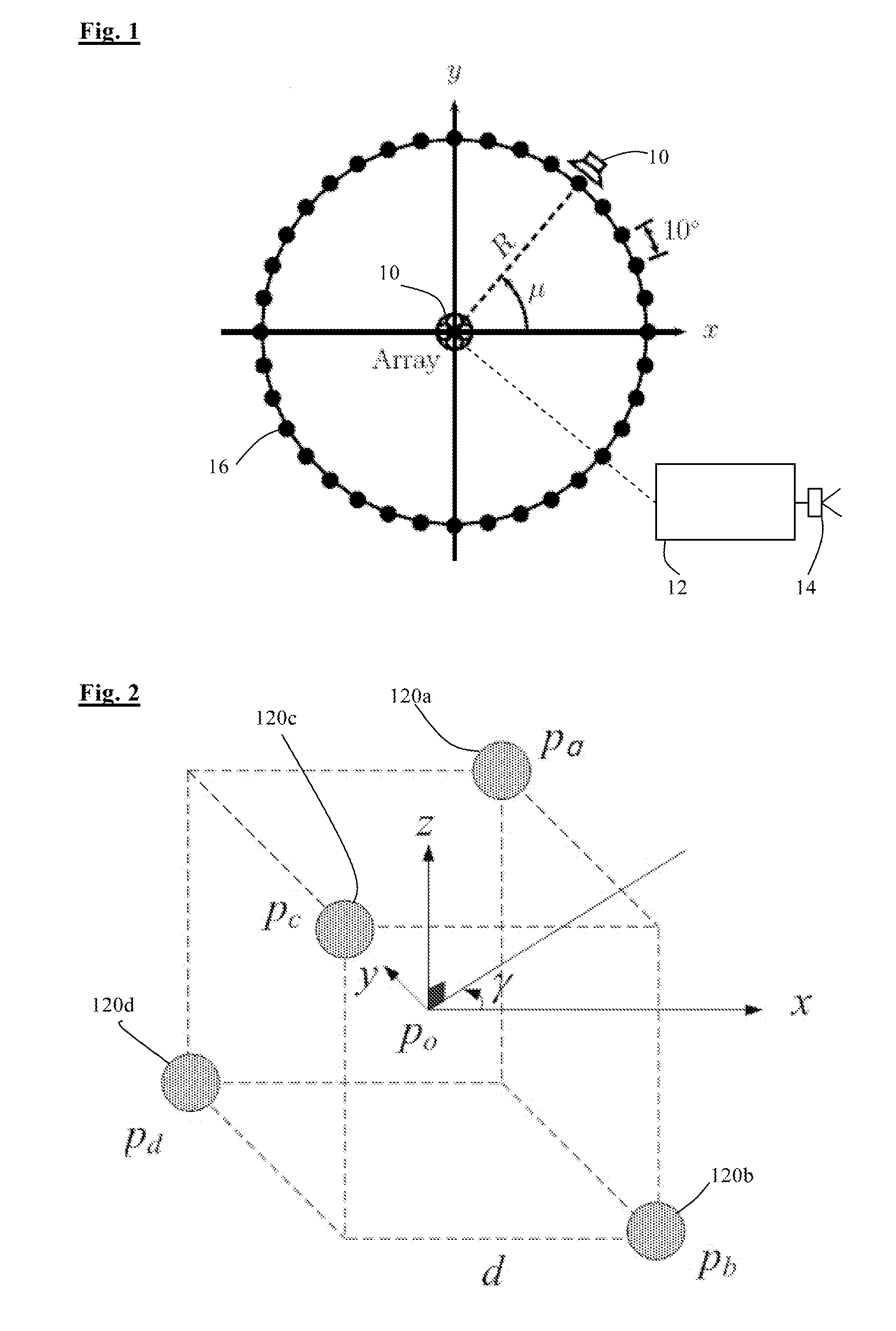
[0045]Referring to FIG. 1, an audio source separation system according to the invention comprises a microphone array 10, a processing system, in this case a personal computer 12, arranged to receive audio signals from the microphone array and process them, and a speaker system 14 arranged to generate sounds based on the processed audio signals. The microphone array 10 is located at the centre of a circle of 36 nominal source positions 16. Sound sources 18 can be placed at any of these positions and the system is arranged to separate the sounds from each of the source positions 16. Clearly in a practical system the sound source positions could be spaced apart in a variety of ways.

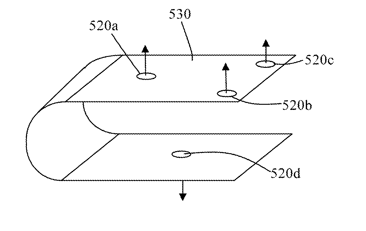
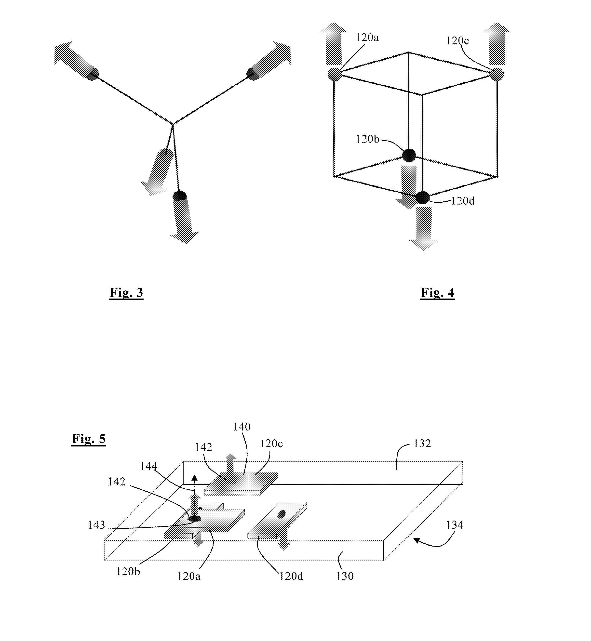
[0046]Referring to FIG. 2, the microphone array 10 comprises four microphones 120a, 120b, 120c, 120d placed at positions which correspond to the four non-adjacent corners of a cube of side length d. This geometry forms a tetrahedral microphone array.

[0047]Let us consider a plane wave arriving from the direct...

second embodiment

[0064]Referring to FIG. 6, in the invention, the four microphones 220a, 220b, 220c, 220d are again all mounted on a common support member 230, but in this case the support member 230 is in the form of a flexible strip of sheet material. The microphones are all mounted on the same side 232 of the strip 230, but the first pair of microphones 220a, 220c is mounted on a first part 230a of the strip, and the second pair of microphones 220b, 220d is mounted on a second part 230b of the strip. The strip 230 is folded so that the two parts 230a, 230b are parallel to each other, with the side 230 on which the microphones are mounted being on the outside so that the two pairs of microphones face away from each other. The final spacing between the two parts 230a, 230b of the strip 230 is such that the diaphragm centres in the four microphones are equidistant from each other as in the previous embodiment. Referring to FIG. 6a, this can be achieved by folding the support member 230 around a rigi...


PUM


Abstract

A system for directionally selective sound reception comprises an array of pressure sensors each arranged to output a pressure signal indicative of pressure, and processing means arranged to receive the pressure signals, identify a plurality of frequency components of the signals, identify at least one source direction, and identify at least one of the components as coming from the source direction. The sensor array comprises support means having two opposite sides and four sensors, at least one of the sensors being supported on each of the sides of the support means.

Description

FIELD OF THE INVENTION[0001]The present invention relates to systems for the separation of a mixture of sounds from different sound sources, and in particular to the design of microphone arrays in such systems.BACKGROUND TO THE INVENTION[0002]The separation of convolutive mixtures aims to estimate the individual sound signals in the presence of other such signals in reverberant environments. As sound mixtures are almost always convolutive in enclosures, their separation is a useful pre-processing stage for speech recognition and speaker identification problems. Other direct application areas also exist such as in hearing aids, teleconferencing, multichannel audio and acoustical surveillance.[0003]Our earlier patent application published as WO 2009 / 050487 discloses a system for separating a mixture of acoustic signals from a plurality of sources which comprises a sensor array comprising a plurality of pressure sensors and a processor arranged to receive signals from the sensors, and ...

Claims


Application Information

Patent Timeline
Patent Type & Authority Applications(United States)
IPC IPC(8): H04R1/08
CPCH04R2430/00H04R1/08H04R1/406H04R3/005H04R2201/401H04R25/405H04R2201/405H04R2430/20H04R1/04H04M3/5125
Inventor NUGENT, DAVIDGUNEL, BANU
Owner UNIVERSITY OF SURREY
Why Eureka
Try Eureka