Power door actuation system

a technology of power door and actuation system, which is applied in the direction of doors, wing accessories, hinges, etc., can solve the problems of limited application of conventional power door actuation system, drawback relates to packaging requirements, etc., and achieve the effect of reducing or eliminating the impingement of system components

Active Publication Date: 2015-03-05
MAGNA CLOSURES INC
View PDF14 Cites 96 Cited by
  • Summary
  • Abstract
  • Description
  • Claims
  • Application Information

AI Technical Summary

Benefits of technology

[0011]It is an aspect of the present disclosure to provide a power door actuation system for swing doors in motor vehicles that can be effectively packaged within the cavity of the door and cooperatively interact with a door hinge.
[0012]It is another aspect of the present disclosure to provide a power door actuation system for swing doors in motor vehicles that can be packaged and oriented to have only a small effect on the door's mass moment of inertia relative to a pivot axis of the door hinge.
[0017]Based on these and other aspects and objectives of the present disclosure, a power swing door actuation system is provided for moving a passenger door of a motor vehicle about a pivot axis between open and closed positions relative to a vehicle body. The system includes a power-operated actuator mechanism which is connectable within an internal cavity of the passenger door in close proximity to an upper door hinge, and a rotary drive mechanism rotatively driven by the power-operated actuator mechanism and which is connectable to a hinge component of a lower door hinge. The power-operated actuator mechanism may include an electric motor and geartrain assembly secured to a mounting bracket which is adapted to be mounted within the cavity of the passenger door and in close proximity to the upper door hinge. The rotary drive mechanism may include a first coupler driven by a rotary output component of the electric motor and geartrain assembly, a second coupler rigidly secured to a body hinge component of the lower door hinge, and a drive member having a first end drivingly coupled to the first coupler and a second end drivingly coupled to the second coupler. Accordingly, the power door actuation system of the present disclosure is able to effectuate controlled swinging movement of the passenger door between its open and closed positions by transferring a rotational force directly from the door-mounted, power-operated actuator mechanism to the vehicle-mounted, lower door hinge.
[0021]In accordance with these and other embodiments, the electric motor and geartrain assembly is generally vertically oriented within the door cavity and secured to a hinge mounting bracket that, in turn, is rigidly secured in proximity to the door-mounted hinge component of the upper door hinge. As such, the power door actuation system can be packaged in a forward vacant portion of the door's internal cavity, such as forward of the A-pillar glass run channel, so as to reduce or eliminate impingement of the system components with other functional components of the door assembly.

Problems solved by technology

Such swinging passenger doors (“swing doors”) have recognized issues such as, for example, when the vehicle is situated on an inclined surface and the swing door either opens too far or swings shut due to the unbalanced weight of the door.
While such power door actuation systems function satisfactorily for their intended purpose, one recognized drawback relates to their packaging requirements.
As such, the application of such conventional power door actuation systems may be limited, particularly to only those vehicular doors where such an orientation would not cause interference with existing hardware and mechanisms such as for example, the glass window function, the power wiring and harnesses, and the like.

Method used


Image

  • Power door actuation system
  • Power door actuation system
  • Power door actuation system

Examples


Embodiment Construction

[0029]In general, at least one example embodiment of a power door actuation system constructed in accordance with the teachings of the present disclosure will now be disclosed. The example embodiment is provided so that this disclosure will be thorough, and will fully convey the scope to those who are skilled in the art. Numerous specific details are set forth such as examples of specific components, devices, and methods, to provide a thorough understanding of embodiments of the present disclosure. It will be apparent to those skilled in the art that specific details need not be employed, that example embodiments may be embodied in many different forms and that neither should be construed to limit the scope of the disclosure. In some example embodiments, well-known processes, will-known device structures, and well-known technologies are described in detail.

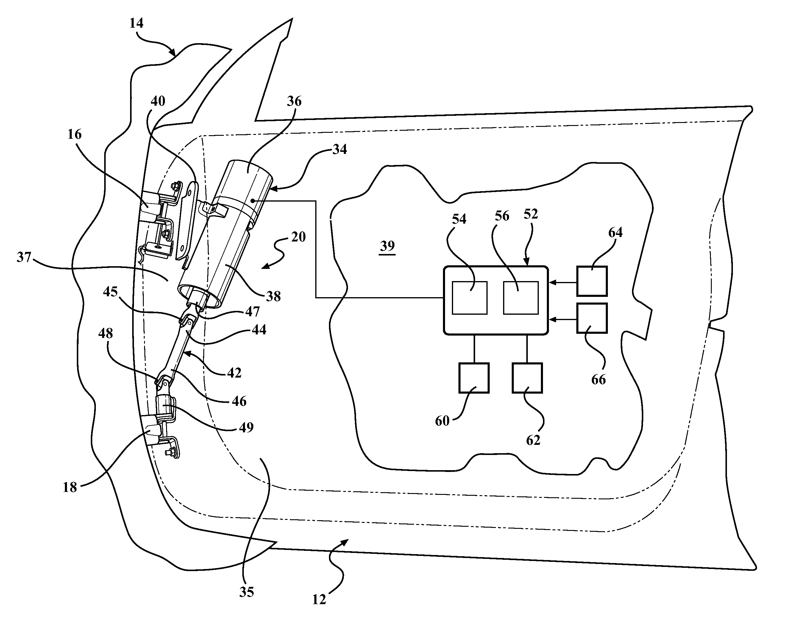
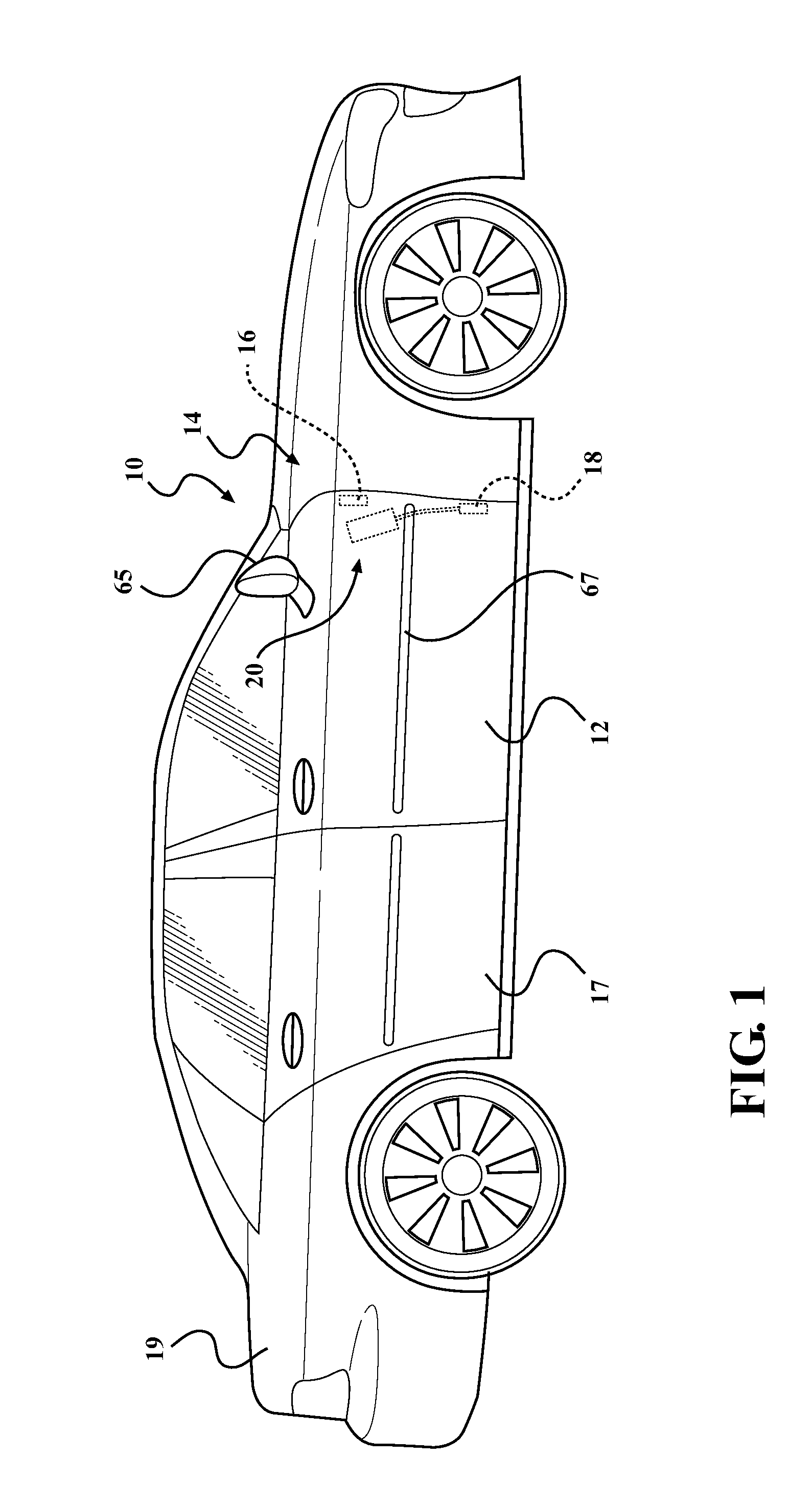
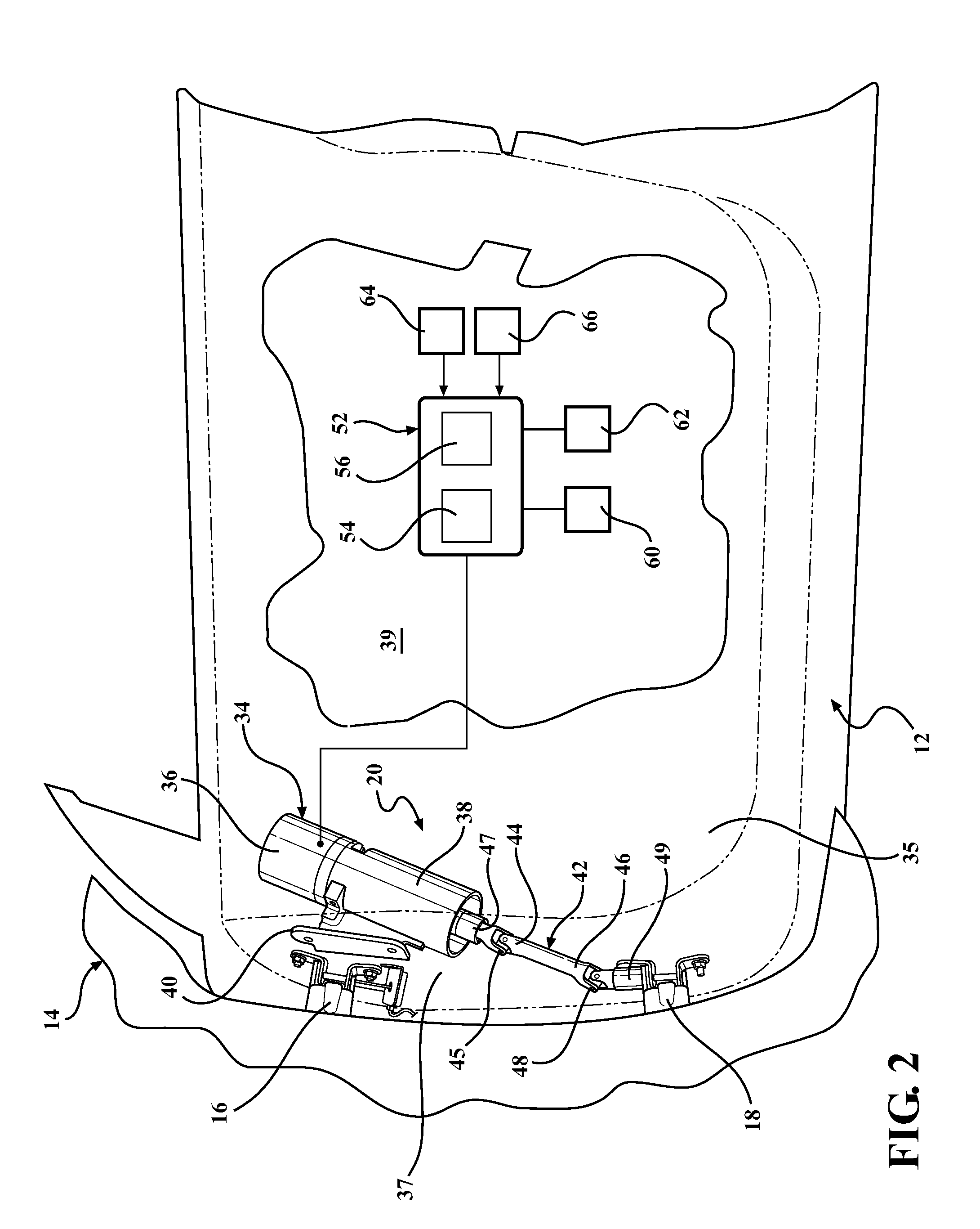
[0030]Referring initially to FIG. 1, an example motor vehicle 10 is shown to include a first passenger door 12 pivotally mounted...


PUM


Abstract

A power door actuation system for moving a vehicle door relative to a vehicle body between an open position and a closed position includes a motor assembly connectable to one of the vehicle door and the vehicle body that is configured to generate a rotational force. A drive shaft is interconnected to the motor assembly and extends from a first end disposed adjacent the motor assembly to a second end. The second end of the drive shaft is rigidly attached to one of a body strap or a door strap of a hinge for transferring the rotational force from the motor assembly to the respective rigidly attached strap to rotate the respective rigidly attached strap relative to the other of the door strap and the body strap for automatically moving the vehicle door between the open and closed positions.

Description

CROSS-REFERENCE TO RELATED APPLICATION[0001]This application claims priority to and the benefit of U.S. Provisional Application No. 61 / 871,937, filed Aug. 30, 2013. The entire disclosure of the above application is incorporated herein by reference.BACKGROUND[0002]1. Field of the Invention[0003]The present disclosure relates generally to door systems for motor vehicles and, more particularly, to a power door actuation system for moving a swinging vehicle door relative to a vehicle body between an open position and a closed position.[0004]2. Related Art[0005]This section provides background information related to the present disclosure which is not necessarily prior art.[0006]The passenger doors on motor vehicles are typically mounted by upper and lower door hinges to the vehicle body for swinging movement about a generally vertical pivot axis. Each door hinge typically includes a door hinge strap connected to the passenger door, a body hinge strap connected to the vehicle body, and a...

Claims


Application Information

Patent Timeline
Patent Type & Authority Applications(United States)
IPC IPC(8): E05F15/10E05F15/20B60J5/04E05F15/18E05D7/00
CPCE05F15/10E05F15/18E05F15/20B60J5/0472E05D7/00E05F15/614B60J5/0413E05F15/611E05F15/655E05F15/73E05Y2400/36E05Y2900/531
Inventor MIU, TRAIANMITCHELL, J. R. SCOTTSABATINI, GABRIELE WAYNE
Owner MAGNA CLOSURES INC
Why Eureka
Try Eureka