Cooling device and heating and colling apparatus

a cooling device and colling technology, applied in lighting and heating apparatus, ventilation systems, heating types, etc., can solve the problems of low discharge flow rate, piezoelectric micro blower, and inability to cool the cooling target object to a temperatur

Active Publication Date: 2015-03-05
MURATA MFG CO LTD
View PDF7 Cites 26 Cited by
  • Summary
  • Abstract
  • Description
  • Claims
  • Application Information

AI Technical Summary

Benefits of technology

[0046]The present invention can provide a cooling device capable of cooling a cooling target object to a temperatu

Problems solved by technology

Therefore, the piezoelectric micro blower in Patent Document 1 cannot cool the cooling target object to a temperature lower than the environment temperature.
Due to this, a discharge flow rate is low and it takes a long time to co

Method used


Image

  • Cooling device and heating and colling apparatus
  • Cooling device and heating and colling apparatus
  • Cooling device and heating and colling apparatus

Examples


first embodiment

[0059]Hereinafter, an analyzing device 10 according to a first embodiment of the present invention is described.

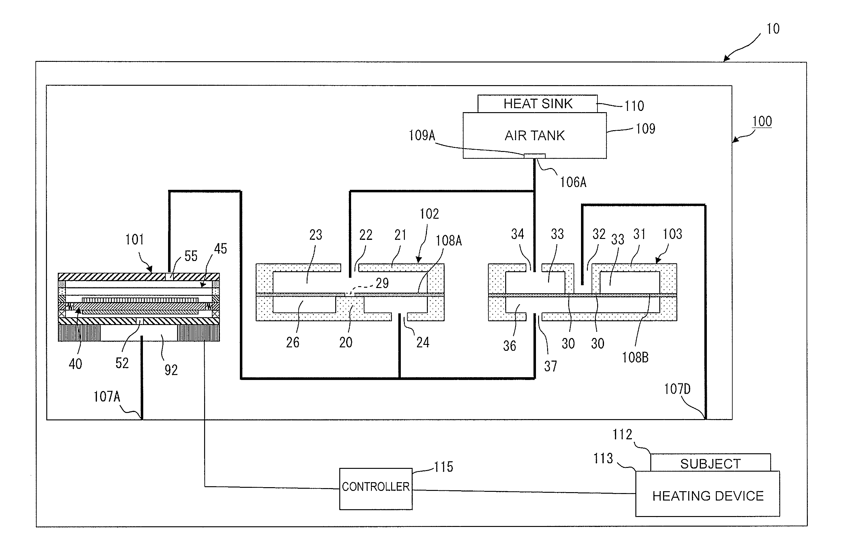
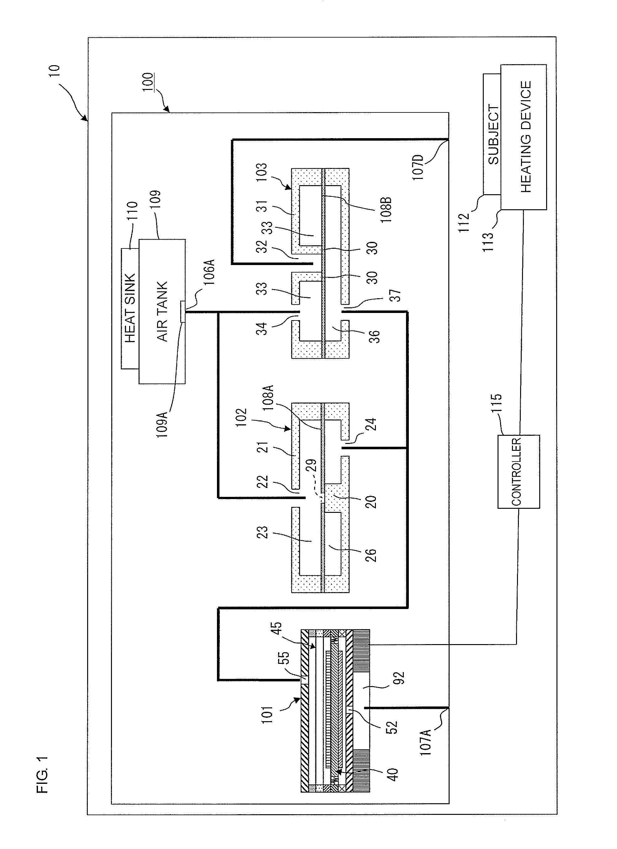
[0060]FIG. 1 is a block diagram illustrating the configuration of a main part of the analyzing device 10 in the first embodiment of the invention. The analyzing device 10 includes a heating device 113, a cooling device 100, and a controller 115. The analyzing device 10 is a device that analyzes a base sequence of nucleic acid such as DNA and RNA, for example.

[0061]A subject 112 is placed on the heating device 113 by a transportation unit (not illustrated). The subject 112 is a container accommodating DNA. In general, analysis of the base sequence of the DNA is performed after the DNA is heated to be denatured.

[0062]The cooling device 100 includes a piezoelectric pump 101, a check valve 102, an exhaust valve 103, and an air tank 109. The cooling device 100 sends air to the subject 112 on the heating device 113 so as to cool the subject 112.

[0063]The air tank 109 is a tank f...

second embodiment

[0152]Hereinafter, an air blower apparatus 11 according to a second embodiment is described.

[0153]FIG. 11 is a block diagram illustrating the configuration of a main part of the air blower apparatus 11 in the second embodiment of the invention. The air blower apparatus 11 includes a cooling device 200 and a controller 215. The air blower apparatus 11 is used as a cold spray, for example.

[0154]The cooling device 200 includes a piezoelectric pump 201, a check valve 202, an exhaust valve 203, a discharge nozzle 204, and an air tank 209. The cooling device 200 sends the air to a subject (not illustrated) so as to cool the subject.

[0155]The air tank 209 is a pressure-tight container for accommodating the air. The air tank 209 is made of a material having good heat conductivity, such as aluminum or the like.

[0156]The subject corresponds to a “cooling target object” in the invention. The check valve 202 corresponds to a “check valve” in the invention and the exhaust valve 203 corresponds t...


PUM


Abstract

An analyzing device includes a heating device, a cooling device, and a controller. The cooling device includes a piezoelectric pump, a check valve, an exhaust valve, and an air tank. The analyzing device heats a subject by the heating device. The cooling device drives the piezoelectric pump while the heating device heating the subject. With this, the outside air is sucked through a suction port and the air that is discharged from the piezoelectric pump is accommodated in the air tank through the check valve. Then, the pressure in the air tank is increased. Thereafter, the cooling device stops driving of the piezoelectric pump. With this, the air in the air tank is discharged toward the subject via the exhaust valve so as to cool the subject.

Description

CROSS REFERENCE TO RELATED APPLICATIONS[0001]The present application is a continuation of PCT / JP2013 / 061826 filed Apr. 23, 2013, which claims priority to Japanese Patent Application No. 2012-107904, filed May 9, 2012, the entire contents of each of which are incorporated herein by reference.FIELD OF THE INVENTION[0002]The present invention relates to a cooling device that sends air toward a cooling target object so as to cool the cooling target object and a heating and cooling apparatus including the cooling device.BACKGROUND OF THE INVENTION[0003]Patent Document 1 discloses a piezoelectric micro blower that sends air toward a cooling target object such as a CPU so as to cool the cooling target object.[0004]FIG. 12 includes cross-sectional views illustrating a main part of the piezoelectric micro blower in Patent Document 1. FIG. 12(a) illustrates an initial state of the piezoelectric micro blower (when voltage is not applied thereto). FIGS. 12(b) to 12(e) illustrate blower operatio...

Claims


Application Information

Patent Timeline
IPC IPC(8): F28F27/02
CPCF28F27/02F04B43/046F28D2021/0029F28F2250/08
Inventor KAMITANI, GAKUHIRATA, ATSUHIKO
Owner MURATA MFG CO LTD
Why Eureka
Try Eureka