Hydrodynamic retarder

Inactive Publication Date: 2015-03-05
ZF FRIEDRICHSHAFEN AG
View PDF9 Cites 4 Cited by
  • Summary
  • Abstract
  • Description
  • Claims
  • Application Information

AI Technical Summary

Benefits of technology

The present invention is about a hydrodynamic retarder that reduces air losses, is cost-effective and simple in design. This design allows for an interruption of the flow between the rotor and stator, which helps to minimize air turbulence and air losses during operation. The retarder can also be designed to have a minimum axial overlap between the rotor and stator blades, further reducing air turbulence. Additionally, the retarder can be eliminated entirely in situations where air is not necessary for braking, simplifying the system and reducing costs.

Problems solved by technology

However, even when a hydrodynamic retarder is operating while empty, i.e. when the toroidal space is not filled, a certain braking torque is produced by it which is caused by forced air circulation between the rotor and the stator.

Method used


Image

  • Hydrodynamic retarder
  • Hydrodynamic retarder
  • Hydrodynamic retarder

Examples


Embodiment Construction

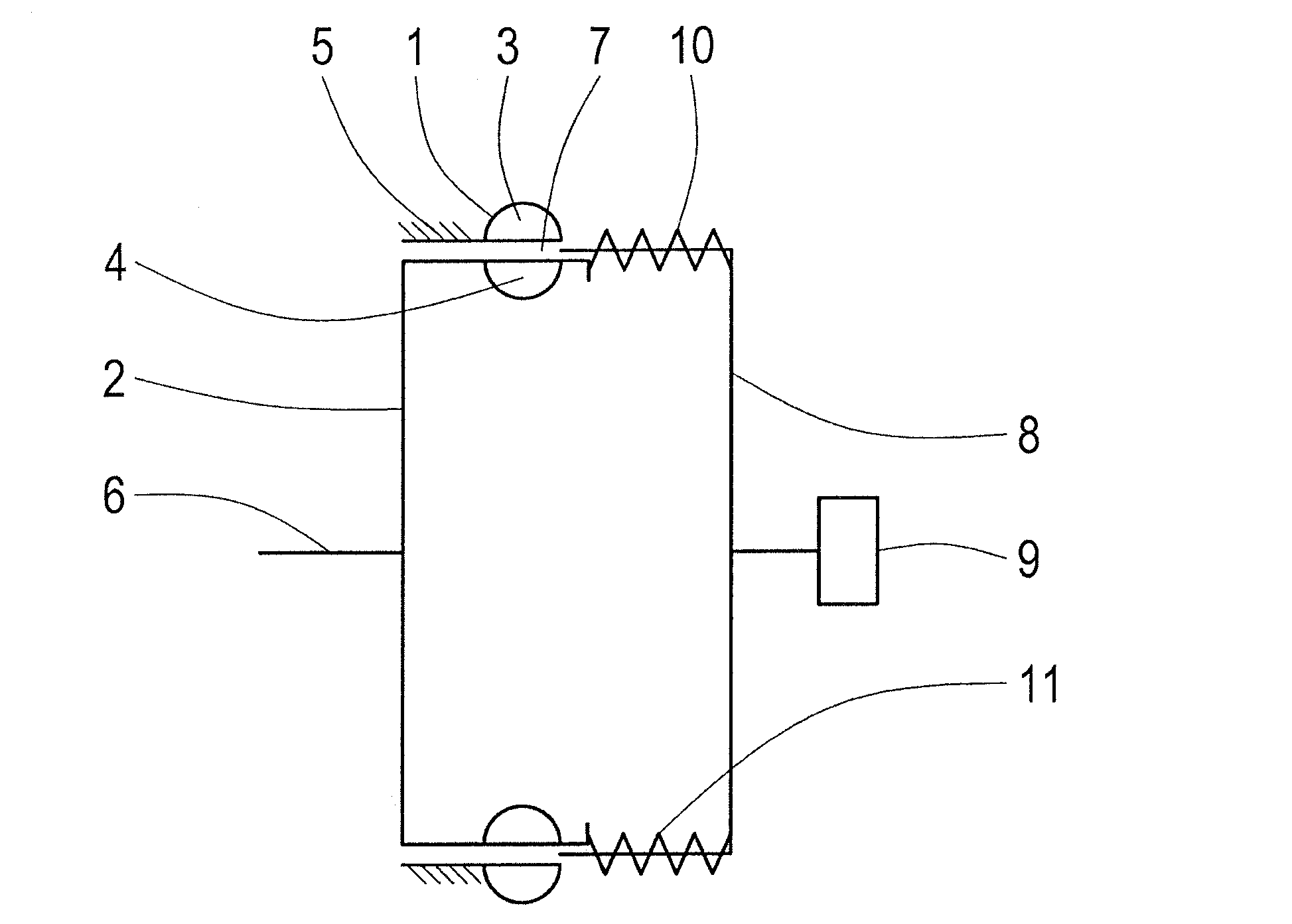
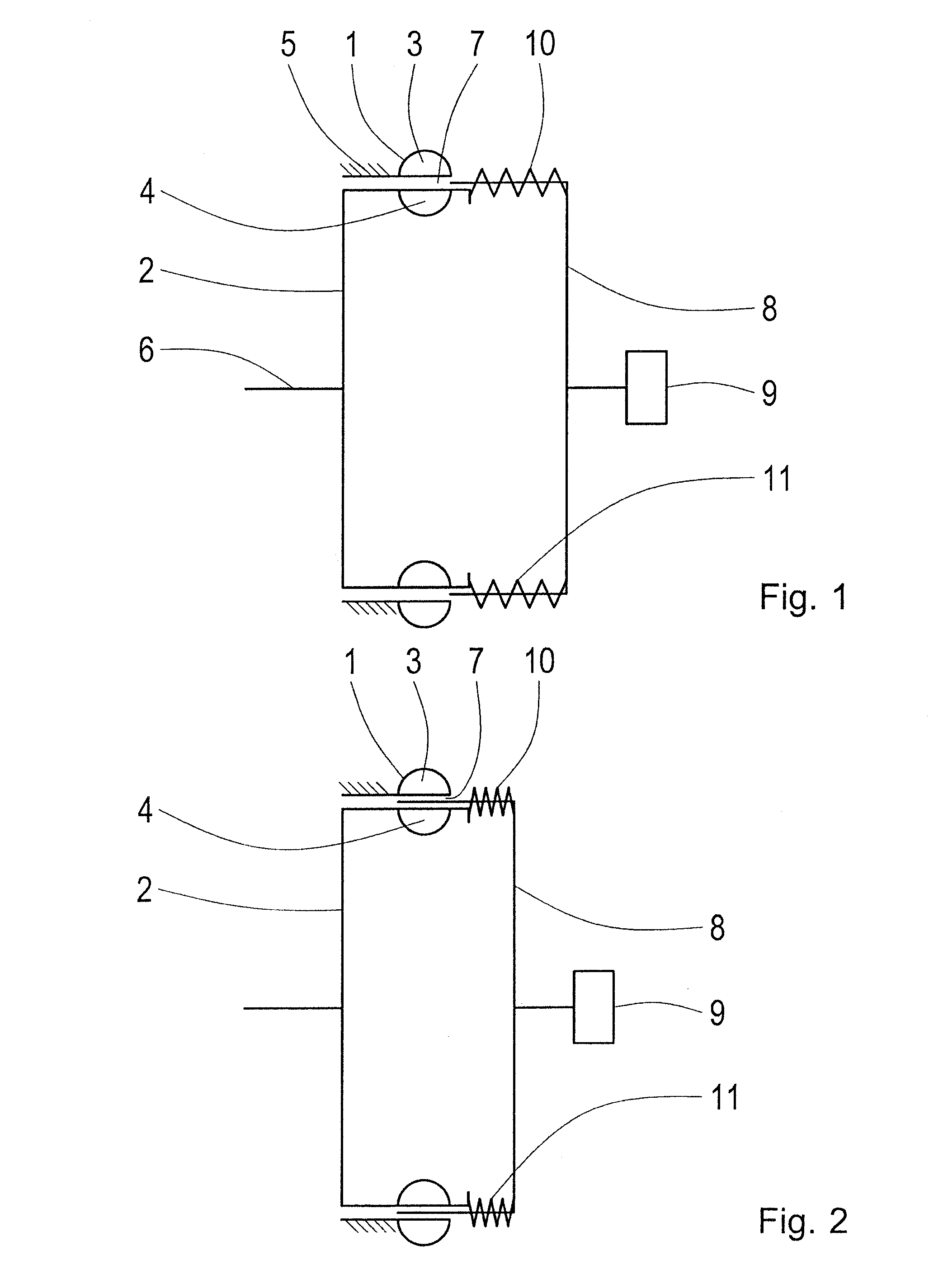
[0026]FIG. 1 shows a schematic representation of a hydrodynamic retarder which can be used in a drive-train of a motor vehicle, in particular a commercial vehicle. The retarder comprises a stator 1 and a rotor 2, each fitted with respective blades 3 and 4. As can also be seen, the stator 1 and so too therefore its blades 3 are attached fixed to a housing 5 of the retarder, whereas the rotor 2 is mounted to rotate on a rotor shaft 6.

[0027]As a special feature the rotor 2 and the stator 1 are arranged radially relative to one another, with the rotor 2 running radially inside the stator 1. Thus, the blades 3 and 4 too are radially opposite one another with the blades 3 of the stator 1 directed radially inward while, in contrast, the blades 4 of the rotor 2 extend radially outward. In a manner whose principle is known to those familiar with the field, a braking torque is produced on the rotor 2 and hence on the rotor shaft 6 when a fluid present in a toroidal space 7 formed between the ...


PUM


Abstract

A hydrodynamic retarder having a rotor (2) and a stator (1). The rotor (2) and the stator (1) are arranged radially relative to one another. An interruption mechanism is provided for interrupting the fluid coupling between the rotor (2) and the stator (1).

Description

[0001]This application claims priority from German patent application serial no. 10 2013 217 551.5 filed Sep. 3, 2013.FIELD OF THE INVENTION[0002]The invention concerns a hydrodynamic retarder, comprising a rotor and a stator. Furthermore, the invention concerns a drive-train of a motor vehicle having a hydrodynamic retarder of the above type.BACKGROUND OF THE INVENTION[0003]Hydrodynamic retarders are used, in particular, in commercial vehicles as wear-free permanent brakes. To produce a braking torque they use the flow energy of a liquid held in a toroidal space between a stator and a rotor. Inside the toroidal space the spinning rotor picks up the liquid by means of its blades, and the liquid then impinges on the blades of the stator, thereafter returning back again to the rotor blades. By virtue of this a braking torque is exerted on the rotor, the size of this braking torque usually being governed by the quantity of liquid present in the toroidal space. However, even when a hydr...

Claims


Application Information

Patent Timeline
IPC IPC(8): F16D57/04
CPCF16D57/04B60T10/02B60T1/087
Inventor WOLFLE, BERND
Owner ZF FRIEDRICHSHAFEN AG
Why Eureka
Try Eureka