Radar apparatus

a radar and apparatus technology, applied in the direction of reradiation, measurement devices, instruments, etc., can solve the problems of reducing the azimuth angle detection performance of the target and increasing the calculation amount of the radar apparatus, so as to suppress the increase of the calculation amount and reduce the sidelobe

Active Publication Date: 2015-03-05
PANASONIC CORP
View PDF0 Cites 70 Cited by
  • Summary
  • Abstract
  • Description
  • Claims
  • Application Information

AI Technical Summary

Benefits of technology

[0015]The disclosure can reduce sidelobes in the cross-range direction while suppre...

Problems solved by technology

However, large sidelobes in the cross-range direction to make discrimination from a case that plural targets having different reception levels exist difficult, as a result of which the target detection performance in the azimuth angle direction is lowered.
O...

Method used


Image

  • Radar apparatus
  • Radar apparatus
  • Radar apparatus

Examples


embodiment 1

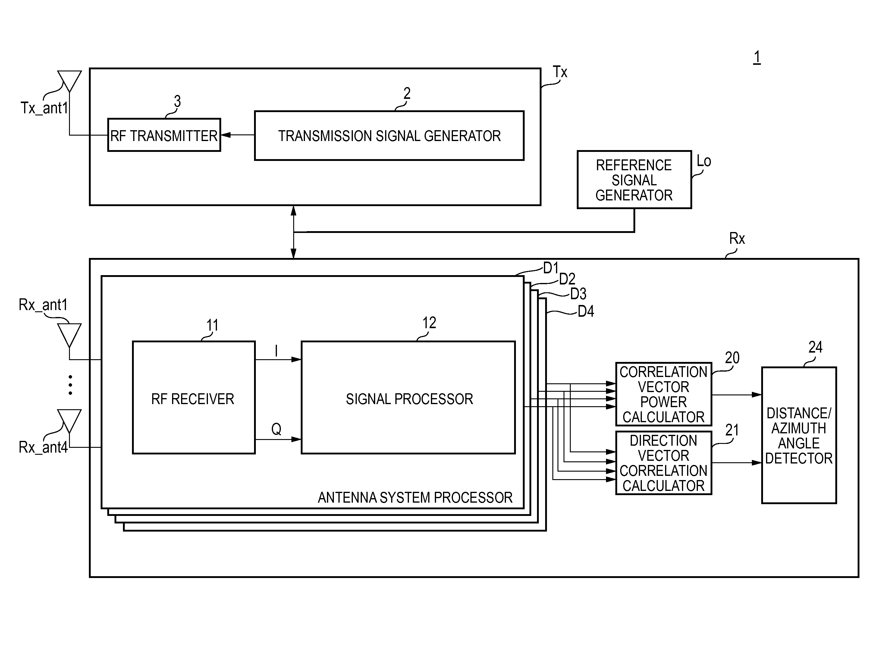
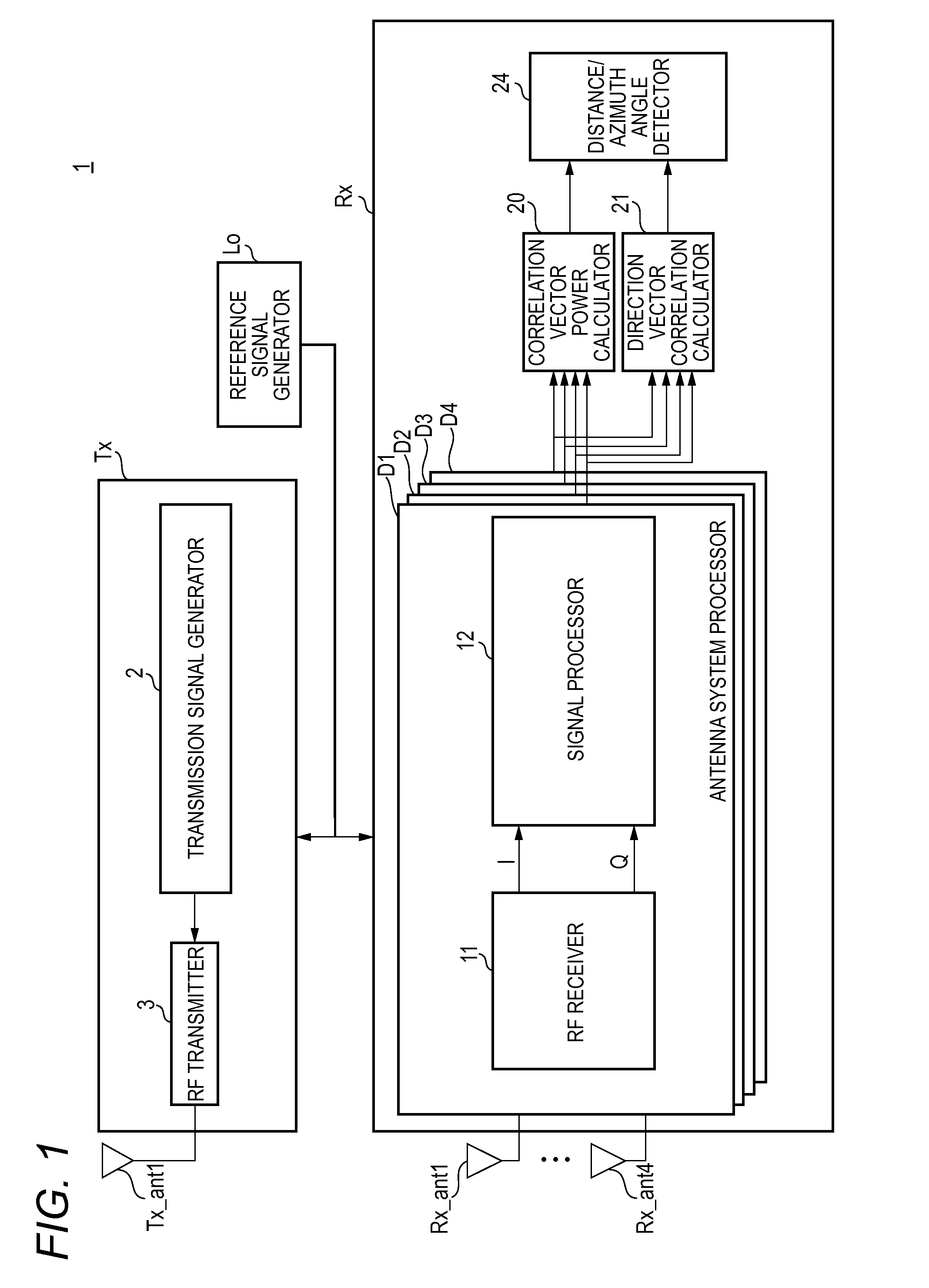
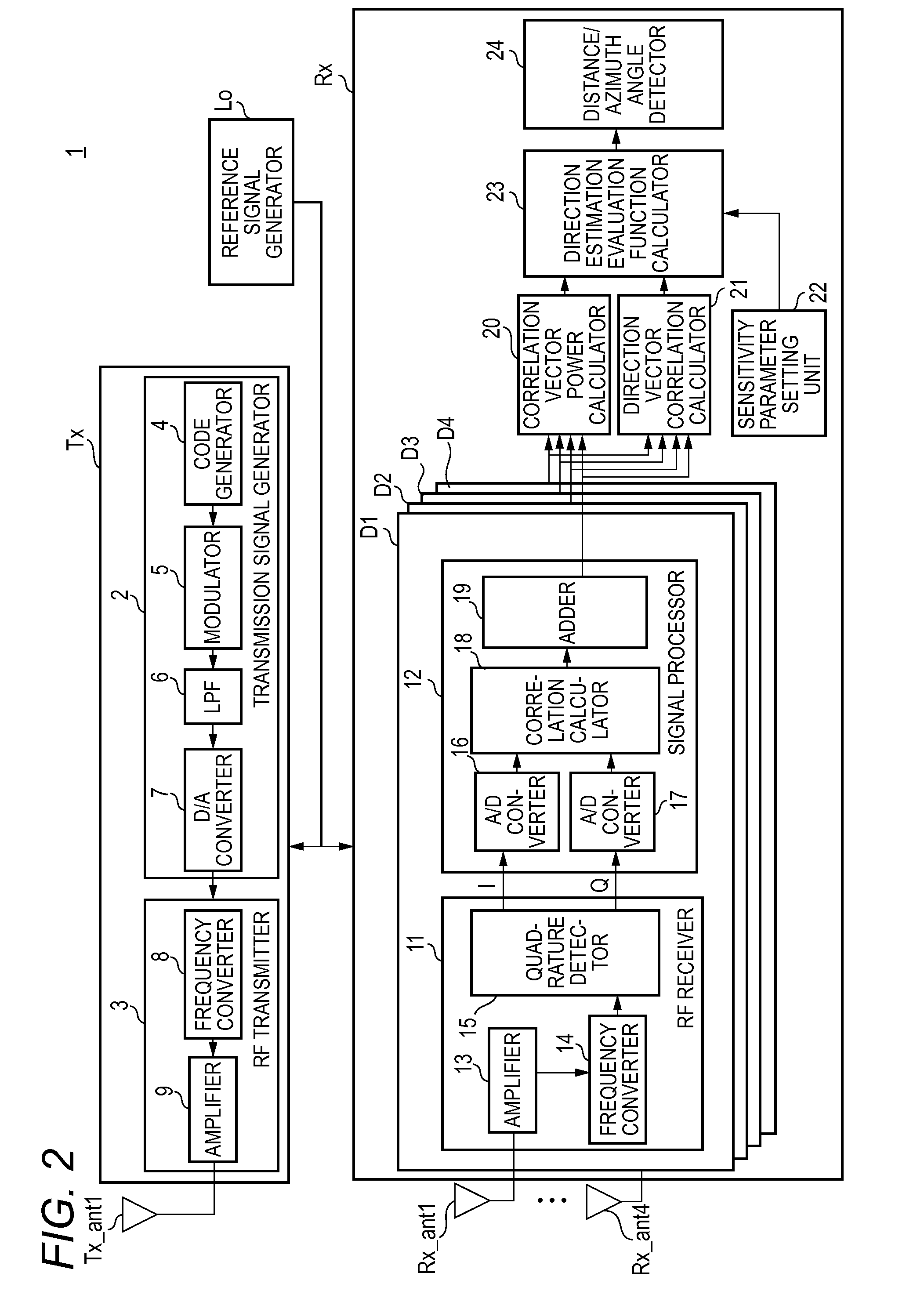
[0039]How a radar apparatus 1 according to a first embodiment is configured and operates will be described with reference to FIGS. 1 to 6. FIG. 1 is a block diagram showing the internal configuration of the radar apparatus 1 according to the first embodiment in a simplified manner. FIG. 2 is a block diagram showing the internal configuration of the radar apparatus 1 according to the first embodiment in detail. FIG. 3 illustrates a relationship between transmission intervals and transmission cycles of a radar transmission signal.

[0040]The radar apparatus 1 transmits (radiates) a radio-frequency radar transmission signal generated by a radar transmitter Tx from a transmission antenna Tx_ant1. The radar apparatus 1 receives, with an array antenna (e.g., four reception antennas Rx_ant1 to Rx_ant4 shown in FIG. 1), a reflection wave signal which is a radar transmission signal as reflected by a target (not shown). The radar apparatus 1 performs signal processing on reflection wave signals...

embodiment 2

[0129]Next, a radar apparatus 1A according to a second embodiment will be described with reference to FIG. 9. FIG. 9 is a block diagram showing the internal configuration of the radar apparatus 1A according to the second embodiment in detail. The radar apparatus 1A includes a reference signal generator Lo, a radar transmitter Tx, and a radar receiver RxA.

[0130]The radar receiver Rx has four antenna system processors D1, D2, D3, and D4 (four is an example number), an orthogonal beam multiplier 25, a beam selector 26, a correlation vector power calculator 20A, a direction vector correlation calculator 21A, a sensitivity parameter setting unit 22, a direction estimation evaluation function calculator 23A, and a distance / azimuth angle detector 24.

[0131]Elements (and their operations) of the radar apparatus 1A according to this embodiment having the same ones in the radar apparatus 1 according to the first embodiment will be given the same reference symbols as the latter and descriptions...

embodiment 3

[0145]Next, a radar apparatus 1B according to a third embodiment will be described with reference to FIG. 10. FIG. 10 is a block diagram showing the internal configuration of the radar apparatus 1B according to the third embodiment in detail. The radar apparatus 1B includes a reference signal generator Lo, a transmission beam controller Be, a radar transmitter TxB, and a radar receiver RxB.

[0146]The radar transmitter TxB has a transmission signal generator 2, a transmission beam former 27, and a total of N_Tx RF transmitters 31, 32, . . . , 3N_Tx. Transmission antennas Tx_ant1, Tx_ant2, . . . , Tx_antN_Tx are connected to the respective RF transmitters 31, 32, . . . , 3N_Tx.

[0147]The radar receiver RxB has four antenna system processors D1, D2, D3, and D4 (four is an example number), a correlation vector power calculator 20, a direction vector correlation calculator 21B, a sensitivity parameter setting unit 22, a direction estimation evaluation function calculator 23B, and a distanc...


PUM


Abstract

A radar receiver receives reflection wave signals which are a radar transmission signal reflected by a target with plural respective antenna system processors, and estimates an incoming direction of the reflection wave signals. A correlation vector power calculator calculates a correlation vector power based on a correlation vector including outputs of the plural respective antenna system processors. A direction vector correlation calculator calculates a direction vector correlation power on the basis of the correlation vector and a direction vector including information of amplitude and phase deviations that occur between the plural respective antenna system processors for each azimuth angle range of an incoming direction of the reflection wave signals. A distance/azimuth angle detector estimates an azimuth angle of an incoming direction of the refection wave signals based on the correlation vector power and the direction vector correlation power.

Description

TECHNICAL FIELD[0001]The present disclosure relates to a radar apparatus which detects a target on the basis of a reflection wave signal reflected from the target.BACKGROUND ART[0002]Radar apparatus transmit a radio-frequency radar transmission signal to the space from a measuring site, receive a reflection wave signal reflected from a target, and measure at least one of a distance between the measuring site and the target and a direction of the target. In recent years, demand for radar apparatus which can estimate, at a high resolution, a distance to or a signal incoming direction (in a wide range) from a target that may be an automobile or a pedestrian using a short-wavelength radar transmission signal such as a signal of microwaves or millimeter waves has increased.[0003]Among conventional radar apparatus are ones which estimate a signal incoming direction at a higher resolution than the resolution of the beam directivity of each reception antenna by receiving a reflection wave s...

Claims


Application Information

Patent Timeline
IPC IPC(8): G01S13/42G01S7/28G01S13/93G01S13/931
CPCG01S13/42G01S7/2813G01S13/931G01S7/292G01S2013/0245G01S13/48G01S13/685
Inventor KISHIGAMI, TAKAAKI
Owner PANASONIC CORP
Why Eureka
Try Eureka