Apparatus and method for designing display for user interaction

a technology of user interaction and apparatus, applied in the field of apparatus and method for designing a display for user interaction, can solve the problems of many limitations in the implementation of commercialization level quality and the mass production of actual products, inability to completely reconstruct a natural phenomenon based on the visual recognition of a 3d stereoscopic space, inaccurate 3d effect, etc., and achieve the effect of preventing the effect of negative human factors

Active Publication Date: 2015-03-05
ELECTRONICS & TELECOMM RES INST
View PDF6 Cites 37 Cited by
  • Summary
  • Abstract
  • Description
  • Claims
  • Application Information

AI Technical Summary

Benefits of technology

[0027]Accordingly, the present invention has been made keeping in mind the above problems occurring in the prior art, and an object of the present invention is to provide an apparatus and method for designing a display for user interaction, which allow direct interac

Problems solved by technology

However, it is impossible to completely (100%) reconstruct a natural phenomenon based on the visual recognition of a 3D stereoscopic space due to technical limitations.
Holographic display technology designated as an ideal 3D stereoscopic image visualization technology implements a procedure in which a light source or light from the light source is reflected and scattered from the surface of an object and is perceived by human eyes, as in the case of a natural environment, but there are still many limitations in the implementation of a commercialization level quality and the mass production of actual products.
However, a stereoscopic image does not reflect various parameters related to visualization such as the user's viewpoint information, thus representing an inaccurate 3D effect as a primary problem.
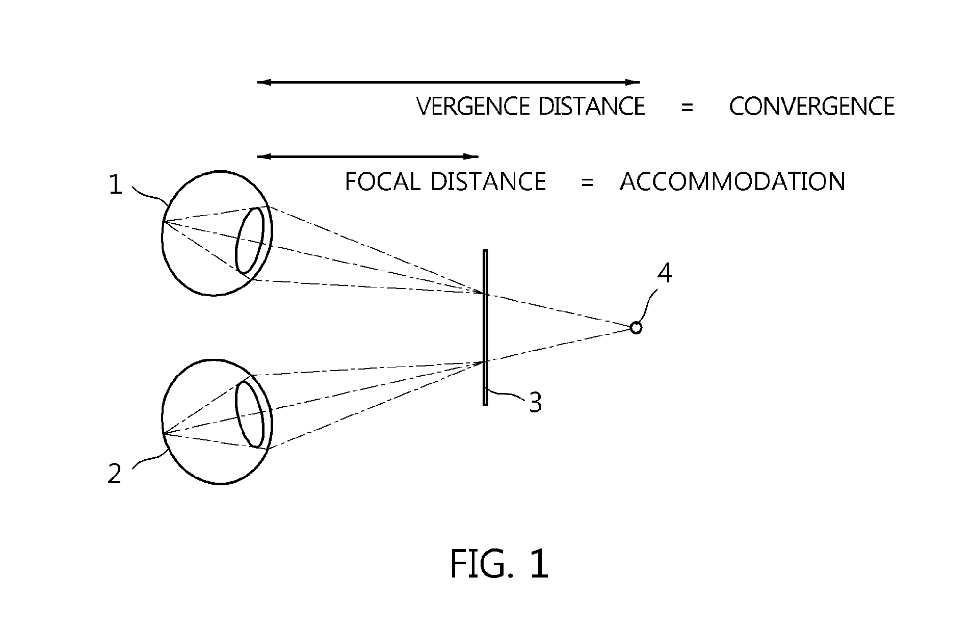
However, continuous experience in most cases in which the latest research results are not desirably reflected/optimized causes human factor-related side effects. FIG. 1 is a diagram showing a convergence-accommodation conflict (VA conflict).
However, when positive or

Method used


Image

  • Apparatus and method for designing display for user interaction
  • Apparatus and method for designing display for user interaction
  • Apparatus and method for designing display for user interaction

Examples


Embodiment Construction

[0049]The present invention is intended to, if given problems are generalized depending on purposes, propose schemes for solving a problem for searching for a utilization method which can analyze the limitations of binocular disparity-based 3D stereoscopic image visualization technology and obtain optimal effects, and a problem for searching for a method of utilizing base technology which can generalize variables for respective users related to the recognition of 3D stereoscopic images and present satisfaction of a predetermined level or more for stereoscopic images.

[0050]Hereinafter, an apparatus and method for designing a display for user interaction according to embodiments of the present invention will be described in detail with reference to the attached drawings. Prior to the following detailed description of the present invention, it should be noted that the terms and words used in the specification and the claims should not be construed as being limited to ordinary meanings ...


PUM


Abstract

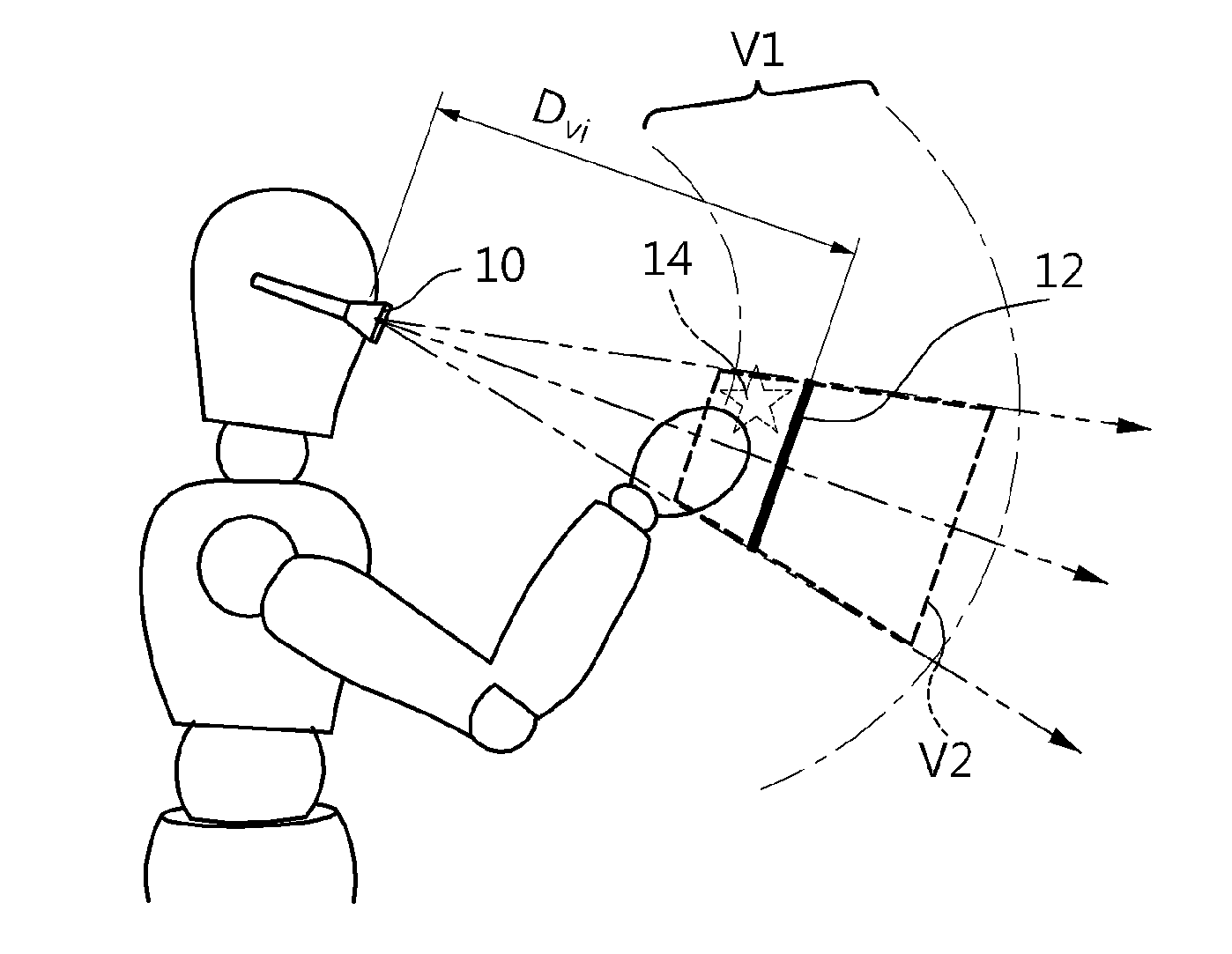
The present invention relates to an apparatus and method for designing a display for user interaction. The proposed apparatus includes an input unit for receiving physical information of a user and a condition depending on a working environment. A space selection unit selects an optimal near-body work space corresponding to the condition received by the input unit. A space search unit calculates an overlapping area between a viewing frustum space, defined by a relationship between a gaze of the user and an optical system of a display enabling a 3D image to be displayed, and the optimal near-body work space selected by the space selection unit. A location selection unit selects a location of a virtual screen based on results of calculation. An optical system production unit produces an optical system in which the virtual screen is located at the location selected by the location selection unit.

Description

CROSS REFERENCE TO RELATED APPLICATION[0001]This application claims the benefit of Korean Patent Application No. 10-2013-0105329, filed on Sep. 3, 2013, which is hereby incorporated by reference in its entirety into this application.BACKGROUND OF THE INVENTION[0002]1. Technical Field[0003]The present invention relates generally to an apparatus and method for designing a display for user interaction and, more particularly, to an apparatus and method for designing a display for three-dimensional (3D) user interaction in a near-body space.[0004]2. Description of the Related Art[0005]A procedure in which human beings visually recognize an object as a three-dimensional (3D) stereoscopic image is influenced by a variety of visual factors.[0006]Since human beings have two eyes on left and right sides of their faces, binocular disparity information occurs between images of external world that are observed, and such images are recognized as a single 3D stereoscopic image by the brain. The pr...

Claims


Application Information

Patent Timeline
IPC IPC(8): G06F3/0481G06T19/00G06F3/01
CPCG06F3/04815G06T2200/24G06T19/006G06F3/013G02B27/017G06F3/011G06F3/017G06F3/01H04N13/00
Inventor YANG, UNGYEONRYU, SEONGWONLEE, GILHAENGKIM, KIHONG
Owner ELECTRONICS & TELECOMM RES INST
Why Eureka
Try Eureka